ENGINE ASSEMBLY ( 3 )
6) Position the piston head front mark so that it is
facing the front of the cylinder body.
7) Use a piston ring compressor to compress the
piston rings.
Piston Ring Compressor
8) Use a hammer grip to push the piston in until
the connecting rod makes contact with the
crankpin.
At the same time, rotate the crankshaft until the
crankpin is at BDC.
9) Install the connecting rod bearing caps.
The bearing cap front marks must be facing the
front of the engine.
The bearing cap number (at the side of the
bearing cap) and the connecting rod number
must be the same.
Note:
It is absolutely essential that the bearing caps be
installed in the correct direction. Reversing the bearing
cap direction will result in serious engine damage.
10) Apply a coat of engine oil to the threads and
setting faces of each connecting rod cap bolt.
11) Tighten the connecting rod caps to the specified
torque.
Connecting Rod Cap Bolt Torque kgf·m(lb.ft/N·m)
8.0 – 9.0 (57.9 – 65.1/78.4 – 88.2)
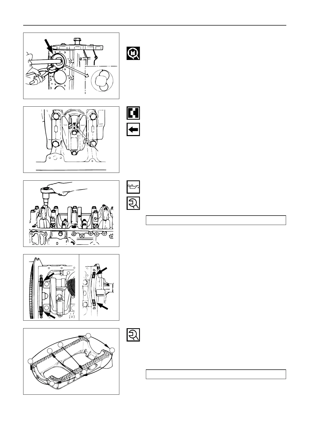
11. Crankcase (if so equipped)
1) Apply sealant to the No. 5 bearing cap arches,
the bearing grooves, and the timing gear case
arches at the positions shown in the illustration.
2) Apply sealant to the crankcase cylinder body
fitting area.
3) Tighten the crankcase bolts to the specified
torque a little at a time in the sequence shown
in the illustration.
Crankcase Bolt Torque kgf·m(lb.ft/N·m)
1.4 – 2.4 (10.1 – 17.3/13.7 – 23.5)
 Loading...