ENGINE ASSEMBLY ( 2 )
49
VALVE GUIDE
Valve Stem and Valve Guide Clearance
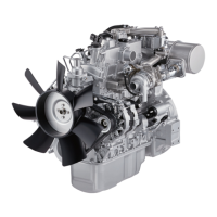
Measuring Method - I
1. With the valve stem inserted in the valve guide, set
the dial indicator needle to “0”.
2. Move the valve head from side to side.
Read the dial indicator.
Note the highest dial indication.
If the measured values exceed the specified limit,
the valve and the valve guide must be replaced as a
set.
Valve Stem Clearance mm(in)
Standard Limit
Intake Valve
0.039 – 0.069 0.20
(0.0015 – 0.0027) (0.008)
Exhaust Valve
0.064 – 0.096 0.25
(0.0025 – 0.0038) (0.0098)
Manifold Fitting Face Warpage mm (in)
Standard Limit
Maximum Grinding
Allwance
0.05
0.2 (0.008) 0.4 (0.016)
(0.002) or less
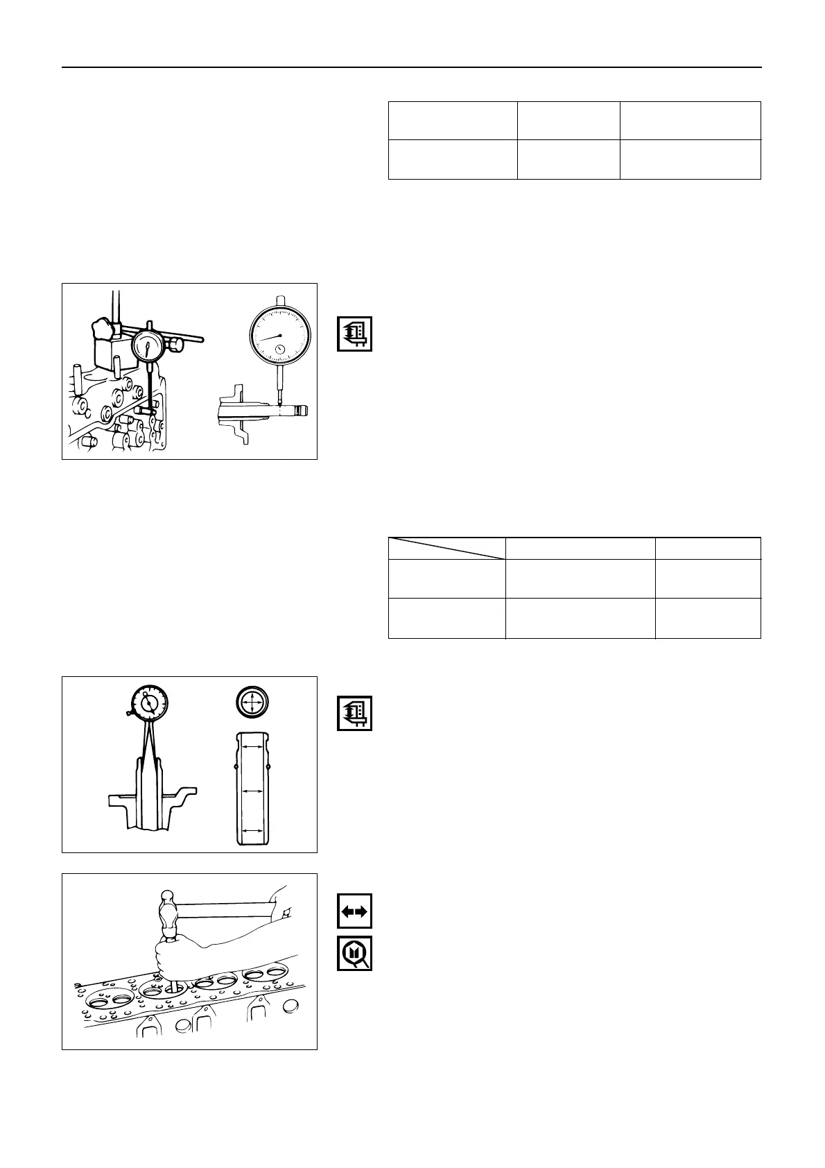
Measuring Method - II
1. Measure the valve stem outside diameter.
Refer to the Item “Valve Stem Outside Diameter”.
2. Use a caliper calibrator or a telescoping gauge to
measure the valve guide inside diameter.
Valve Guide Replacement
Valve Guide Removal
Use a hammer and the valve guide replacer to drive out
the valve guide from the cylinder head lower face.
Valve Guide Replacer: 9-8523-1212-0
 Loading...