MAINTENANCE
VALVE CLEARANCE ADJUSTMENT
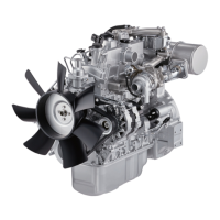
1. Retighten the rocker arm shaft bracket bolts in
sequence as shown in the illustration.
Rocker Arm Shaft Bracket Bolt
Torque kgf·m(lb.ft/N·m)
5.0 – 6.0 (36.2 – 43.4/49.0 – 58.8)
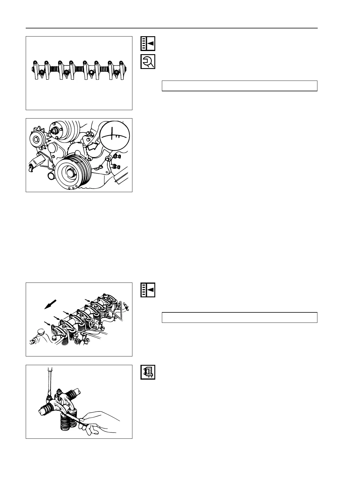
2. Bring the piston in either the No. 1 cylinder or the
No. 4 cylinder to TDC on the compression stroke by
turning the crankshaft until the crankshaft damper
pulley TDC line is aligned with the timing pointer.
3. Check for play in the No. 1 intake and exhaust valve
push rods.
If the No. 1 cylinder intake and exhaust valve push
rods have play, the No. 1 piston is at TDC on the
compression stroke.
If the No. 1 cylinder intake and exhaust valve push
rods are depressed, the No. 4 piston is at TDC on the
compression stroke.
Adjust the No. 1 or the No. 4 cylinder valve clearances
while their respective cylinders are at TDC on the com-
pression stroke.
Valve Clearance mm(in.)
0.40 (0.016)
Loosen each valve clearance adjusting screw as shown
in the illustration. (At TDC on the compression stroke of
the No. 1 cylinder)
Insert a feeler gauge of the appropriate thickness
between the rocker arm and the valve stem end.
4. Turn the valve clearance adjusting screw until a
slight drag can be felt on the feeler gauge.
5. Tighten the lock nut securely.
23
 Loading...