ENGINE ASSEMBLY ( 2 )
5. Install the bearing cap and tighten it to the specified
torque.
Do not allow the connecting rod to move when
installing and tightening the bearing cap.
Connecting Rod Bearing Cap Bolt
Torque kgf·m(lb.ft/N·m)
8.0 – 9.0 (57.9 – 65.1/78.4 – 88.2)
6. Remove the bearing cap.
7. Compare the width of the Plastigage attached to
either the crankshaft or the bearing against the scale
printed on the Plastigage container.
If the measured value exceeds the specified limit,
perform the following additional steps.
1) Use a micrometer to measure the crankpin out-
side diameter.
2) Use an inside dial indicator to measure the
bearing inside diameter.
If the crankpin and bearing clearance exceeds
the specified limit, the crankshaft and/or the
bearing must be replaced.
Crankpin and Bearing Clearance mm(in)
Standard Limit
0.029 – 0.066 0.10
(0.0011 – 0.0026) (0.0039)
70
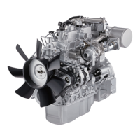
Crankshaft Timing Gear Replacement
Crankshaft Timing Gear Removal
1. Use the crankshaft gear remover 1 to remove the
crankshaft gear 2 .
2. Remove the crankshaft feather key.
Crankshaft Timing Gear Remover: 9-8840-2057-0
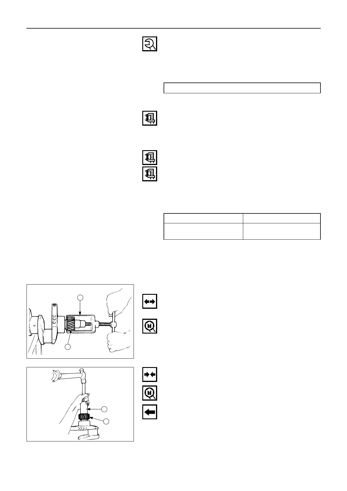
Crankshaft Timing Gear Installation
1. Install the crankshaft gear.
2. Use the crankshaft gear installer 1 to install the
crankshaft gear 2 .
The crankshaft gear timing mark (“X – X”) must be
facing outward.
Crankshaft Gear Installer: 9-8522-0020-0
 Loading...