ENGINE ASSEMBLY ( 2 )
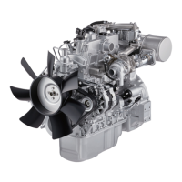
Connecting Rod Side Face Clearance
1. Install the connecting rod to the crankpin.
2. Use a feeler gauge to measure the clearance
between the connecting rod big end side face and
the crankpin side face.
If the measured value exceeds the specified limit,
the connecting rod must be replaced.
Connecting Rod and Crankpin Side Face
Clearance mm(in)
Standard Limit
0.23 (0.009) 0.35 (0.014)
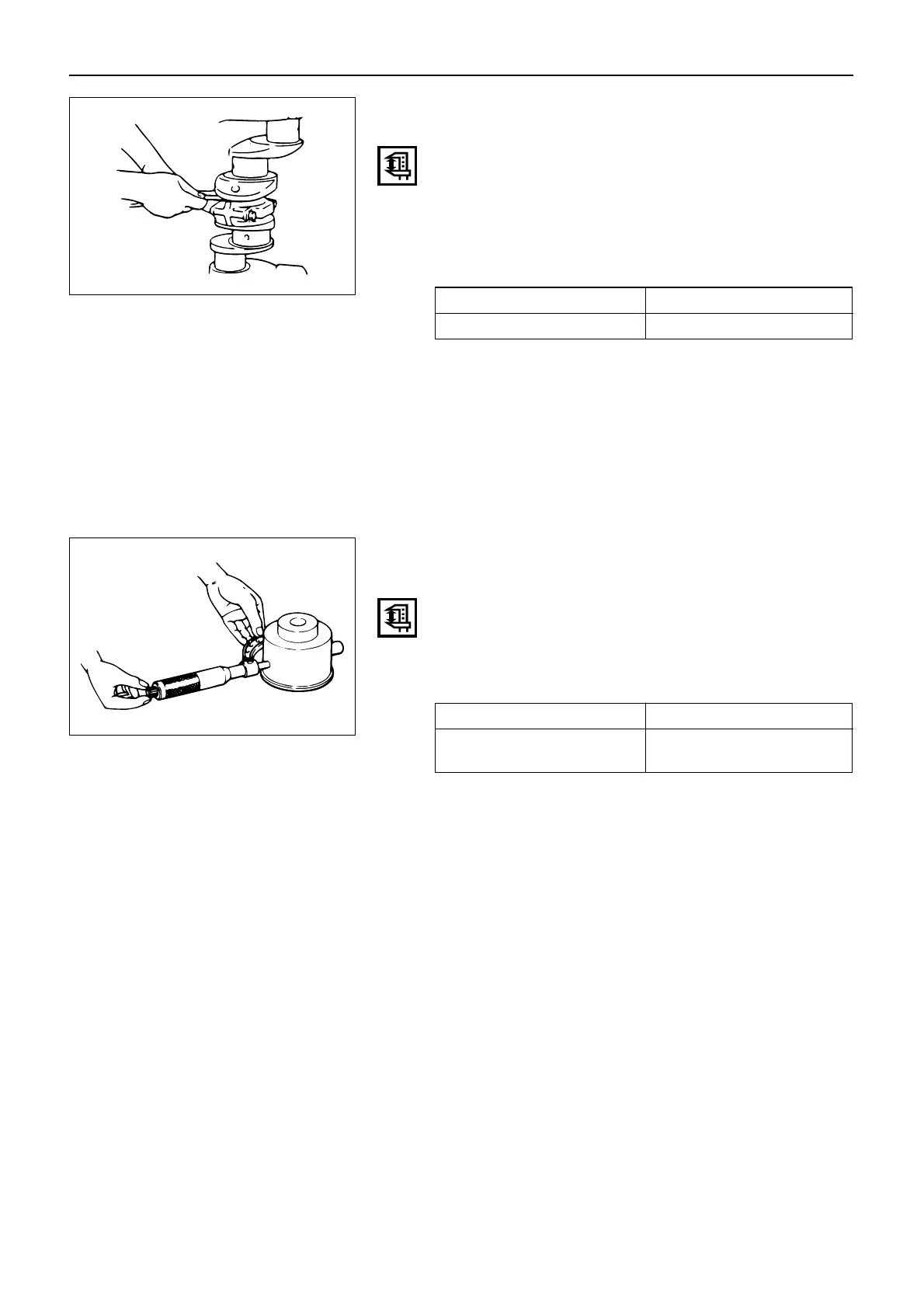
IDLER GEAR SHAFT AND IDLER GEAR
Idler Gear Shaft Outside Diameter
Use a micrometer to measure the idler gear shaft out-
side diameter.
If the measured value is less than the specified limit, the
idler gear must be replaced.
Idler Gear Shaft Outside Diameter mm(in)
Standard Limit
44.95 – 44.98 44.90
(1.770 – 1.771) (1.767)
77
 Loading...