Digital I/O, Analog Outputs, and External Feedback 11-5
Source mode — logic control
The digital outputs can be used as logic inputs to active TTL, low-power TTL, or CMOS
inputs. For this mode of operation, the output lines can source up to 2mA.
CAUTION Each output line can source up to 2mA. Exceeding 2mA may cause damage
to
Model 6514 that is not covered by the warranty.
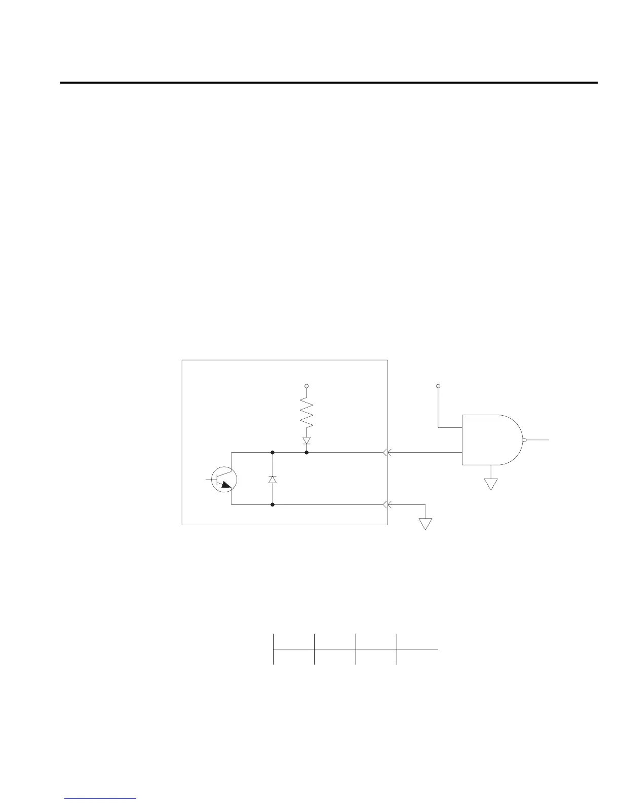
Figure 11-4 shows how to connect a logic device to one of the output lines. When the output
line is set HI, the transistor will turn off (transistor switch open) to provide a reliable logic high
output (>3.75V). When the output line is set LO, the transistor turns on (transistor switch
closed) to route current to digital ground. As a result, a low logic output (0V) is provided at the
output.
If the second input (B) of the NAND gate is connected to another output line of the port, the
output of the NAND gate will go to logic 0 when both digital outputs are set HI.
Setting digital output lines
Digital output lines are set by selecting a decimal value (0 to 15) that corresponds to the 4-bit
BCD pattern of the output. To determine the value, add up the decimal weight values for the
desired HI lines:
For example, to set output lines 3 and 1 HI (0101 bit pattern), set the output value to 5 (4 +1).
Output HI Line: Out 4 Out 3 Out 2 Out 1
Decimal Weight: 8 4 2 1
Model 6514
+5V
1kΩ
Pull Up Resistor
Pin 9
Pin 1
Logic
Device
NAND
B
A
Figure 11-4
AND gate control