Measurement Concepts 2-5
Maximum input levels
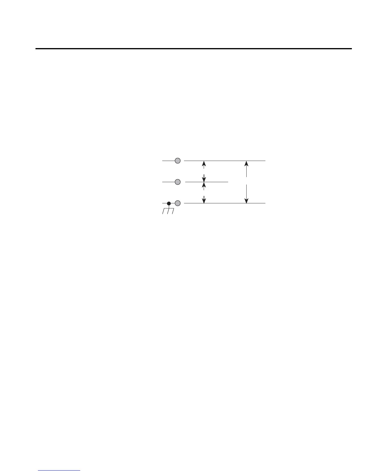
The maximum input levels to Model 6514 are summarized in Figure 2-2.
WARNING The maximum common-mode input voltage, which is the voltage between
the input (HI or LO) and chassis ground, is 500V peak. Exceeding this value
may create a shock hazard.
CAUTION Connecting PREAMP OUT, COMMON, or 2V ANALOG OUTPUT to
earth while floating the input may damage the instrument.
Low noise input cables
When making precision measurements, you should always use low noise cables. The follow-
ing low noise cables are recommended for use with Model 6514:
• Model 237-ALG-2 — This 2-meter low noise triax cable mates directly to the input con-
nector of Model 6514. The other end is terminated with three alligator clips. The clip
with the red boot is input high, black boot is input low or guard, and the green boot is
chassis ground.
• Model 7078-TRX-3 — This 3-foot low noise triax cable is terminated with a 3-slot triax
connector on either end.
• Models 7078-TRX-10 and 7078-TRX-20 — Same as Model 7078-TRX-3 except that
they are 10 feet and 20 feet in length.
NOTE As a general rule, always use the shortest possible cable for volts, amps and ohms
measurements.
Input High
Input Low
Max Input Signal *
500V Peak
Chassis Ground
500V Peak
* Max Input Signal - 250V Peak, DC to 60Hz sine wave
(10 seconds maximum in mA ranges).
Figure 2-2
Maximum input levels

 Loading...


