DISPlay, FORMat, and SYSTem 16-5
Figure 16-1 also shows the byte order of the data string. Data elements not specified by the
:ELEMents command are simply not included in the string.
IEEE-754 single precision format
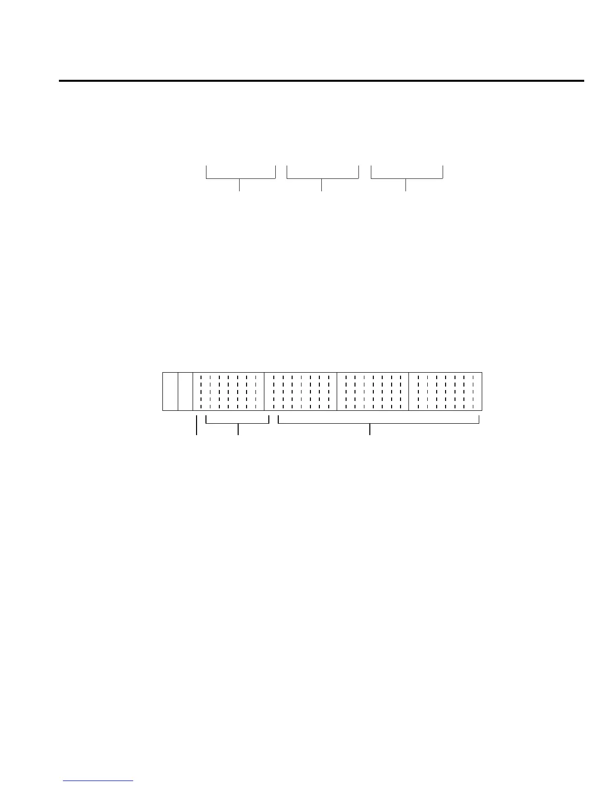
REAL 32 or SREal will select the binary IEEE-754 single precision data format. Figure 16-2
shows the normal byte order format for each data element. For example, if all three data elements
are selected, the data string for each reading conversion is made up of three 4-byte data blocks.
Note that the data string for each reading conversion is preceded by a 2-byte header that is the
binary equivalent of an ASCII # sign and 0. Figure 16-2 does not show the byte for the terminator
that is attached to the end of each data string. Note that the byte order of the data string can be
sent in reverse order (see :BORDer).
During binary transfers, never un-talk Model 6514 until after the data is read (input) to the
computer. Also, to avoid erratic operation, the readings of the data string (and terminator) should
be acquired in one piece. The header (#0) can be read separately before the rest of the string.
The number of bytes to be transferred can be calculated as follows:
Bytes = 2 + (Rdgs x 4) + 1
where; 2 is the number of bytes for the header (#0).
Rdgs is the product of the number of selected data elements, arm count and trigger
count.
4 is the number of bytes for each reading.
1 is the byte for the terminator.
+1.040564E-06, +2.236299E+02, +1.380000E+02
Reading Timestamp Status
Figure 16-1
ASCII data format
Byte 1
70
Header Byte 2
70
Byte 3
70
Byte 4
70
se f
#0
s = sign bit (0 = positive, 1 = negative)
e = exponent bits (8)
f = fraction bits (23)
Normal byte order shown. For swapped byte order,
bytes sent in reverse order: Header, Byte 4, Byte 3
Byte 2, Byte 1.
The header and terminator are sent only once for each READ?.
Figure 16-2
IEEE-754 single
precision data
ormat (32 data
bits)