Digital I/O, Analog Outputs, and External Feedback 11-15
Logarithmic currents
The use of a diode junction in the external feedback path permits a logarithmic current-to-
voltage conversion. This relationship for a junction diode is given by the equation:
V = mkT/q ln(I/I
O
) + I
RB
where; q = unit of charge (1.6022 x 10
-19
)
k= Boltzmann's constant (1.3806 x 10
-23
)
T= temperature (K).
The limitations in this equation center on the factors I
O
, m, and RB. I
O
is the extrapolated cur-
rent for V
O
. An empirical proportional constant, m, accounts for the different character current
conduction (recombination and diffusion mechanisms) within the junction, typically varying
between 1 and 2. Finally, RB constitutes the ohmic bulk resistance of the diode junction mate-
rial. I
O
and RB limit the usefulness of the junction diode at low and high currents respectively.
The factor m introduces non-linearity’s between those two extremes. Because of these limita-
tions, most diodes have a limited range of logarithmic behavior.
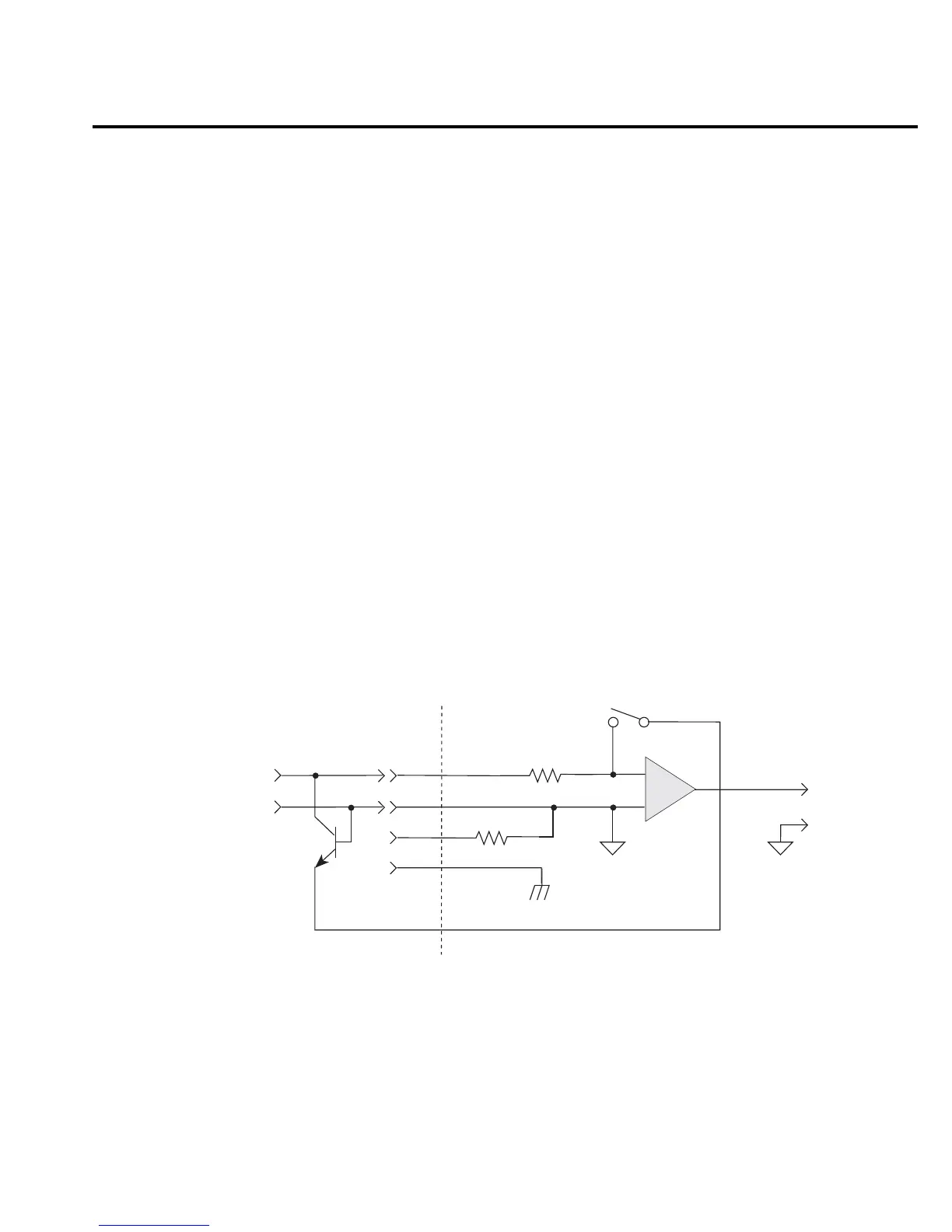
A solution to these constraints is to use a transistor configured as a "transdiode" in the feed-
back path, as shown in Figure 11-9. Analyzing the transistor in this configuration leads to the
relationship:
V = kT/q[ln(I/I
O
) - ln(h
FE
/(1 + h
FE
))]
where; h
FE
is the current gain of the transistor.
From this equation, proper selection of Q1 would require a device with high current gain
(h
FE
), which is maintained over a wide range of emitter currents. Suitable devices for this appli-
cation include Analog Devices AD812 and Precision Monolithics MAT-01. Use the enclosure in
Figure 11-8 to shield the device.
Input
HI
Current
Input
COM
Preamp
Out
Op Amp
+
-
Zero
Check
<1Ω
(Chassis)
LO
S
To Ranging
Amplifier
S
Q1
10MΩ
Model 6514
Figure 11-9
“Transdiode”
logarithmic current
configuration

 Loading...


