Status Structure 13-3
0
2
3
5
6
Cal
10
11
12
13
15
Condition
Register
(Always Zero)
0
2
3
5
6
10
11
12
13
15
Event
Register
0
11 1
2
3
5
6
10
11
12
13
15
Event Enable
Register
&
&
&
&
&
&
&
&
&
&
&
&
&
&
&
&
Logical
OR
3
Trig
7
Idle
11
12
13
Condition
Register
3
7
Idle
11
12
13
Event
Register
3
7
Idle
11
12
13
Register
&
&
&
&
&
&
&
&
&
&
&
&
&
&
Logical
OR
Idle
EAV
QSB
MAV
ESB
RQS/MSS
OSB
Status
Byte
Register
1
EAV
QSB
MAV
ESB
6
OSB
Service
Request
Enable
Register
&
&
&
&
&
&
&
Logical
OR
*STB?
*SRE
*SRE?
Master Summary Status (MSS)
MSB = Measurement Summary Bit
EAV = Error Available
QSB = Questionable Summary Bit
MAV = Message Available
ESB = Event Summary Bit
RQS/MSS = Request for Service/Master Summary Staus
OSB = Operation Summary Bit
Error Queue
Output Queue
Trig Trig
Note : RQS bit is in serial poll byte,
MSS bit is in *STB? response.
1
14 14
OPC
QYE
DDE
EXE
CME
URQ
PON
8
9
8
11
12
13
15
Event
Register
8
9
8
11
12
13
15
Register
&
&
&
&
&
&
&
&
&
&
&
&
&
&
&
&
Logical
OR
(Always Zero)
Operation Complete
Query Error
Device Specific Error
Execution Error
Command Error
User Request
Power On
OPC
QYE
DDE
EXE
CME
URQ
PON
*ESR? *ESE <NRf>
*ESE?
MSB MSB
12
13
12
13
Event
Register
12
13
Register
&
&
&
&
&
&
&
&
&
&
&
&
&
Logical
OR
Condition
Register
11
Calibration Summary
Warn
222
4
10 10 10
Cal
1
Cal
1
Cal
1
11 11 11
Trigger Layer
Command Warning
999
14
15
14
15
14
15
&
&
14 14 14&
15 15 15
&
Calibrating
8
9
Cal
Warn
4
8
9
Cal
Warn
4
8
9
:CONDition? [:EVENt]? :ENABle <NRf>
:ENABle?
Low Limit 1 Fail
High Limit 1 Fail
Low Limit 2 Fail
High Limit 2 Fail
Limits Pass
Reading Available
Reading Overflow
Buffer Available
Buffer Full
LL1F
HL1F
LL2F
HL2F
LP
RAV
ROF
BAV
BFL
(Always Zero)
:CONDition? [:EVENt]? :ENABle <NRf>
:ENABle?
LL1F
HL1F
LL2F
HL2F
LP
RAV
ROF
BAV
BFL
LL1F
HL1F
LL2F
HL2F
LP
RAV
ROF
BAV
BFL
4
Arm Layer Arm
8
4
Arm
8
4
Arm
8
Questionable Event Registers
Event Enable
Standard Event Registers
Event Enable
Measurement Event Registers
Event Enable
Operation Event Registers
:CONDition? [:EVENt]? :ENABle <NRf>
:ENABle?
0
00
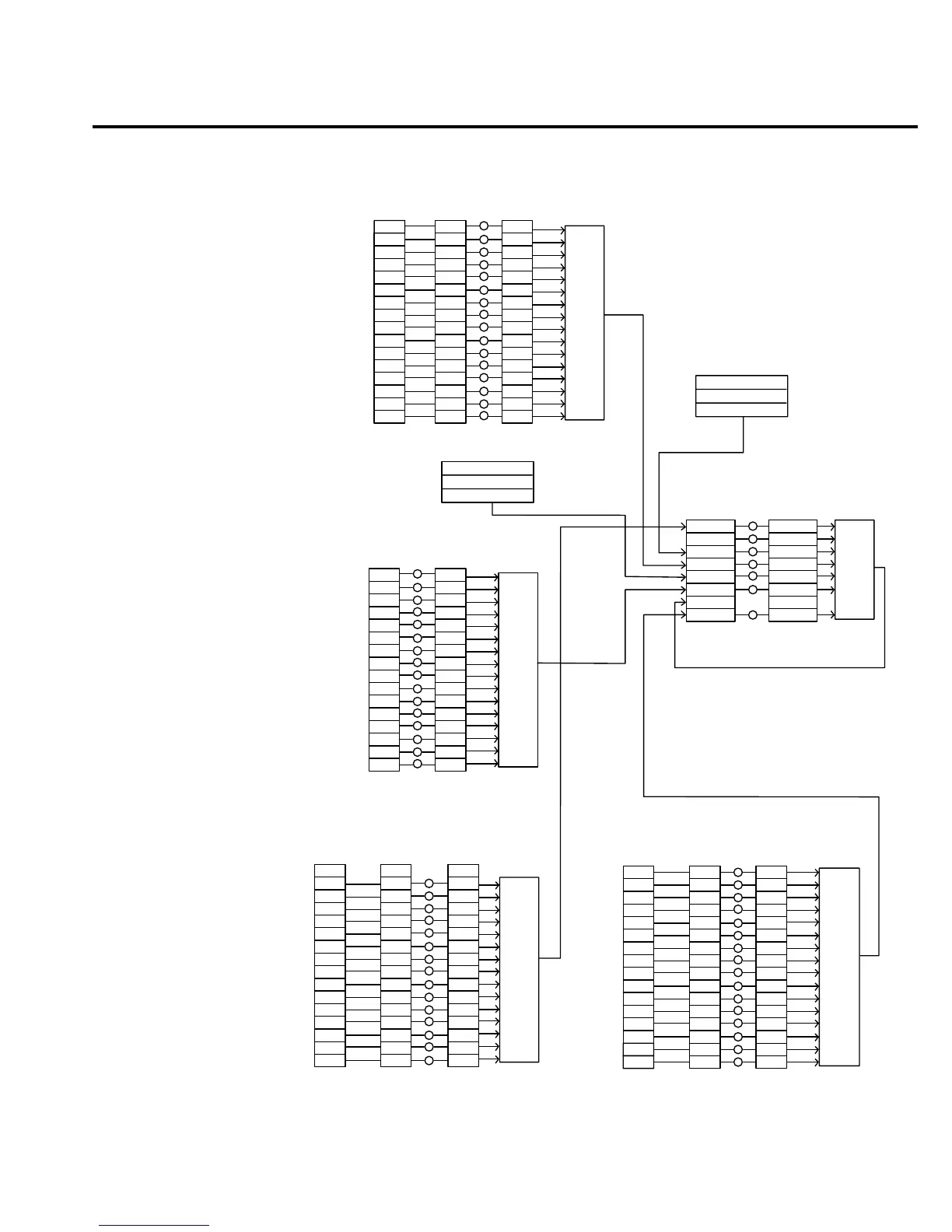
Figure 13-1
6514 status
mode structure

 Loading...


