Triggering 9-11
External triggering
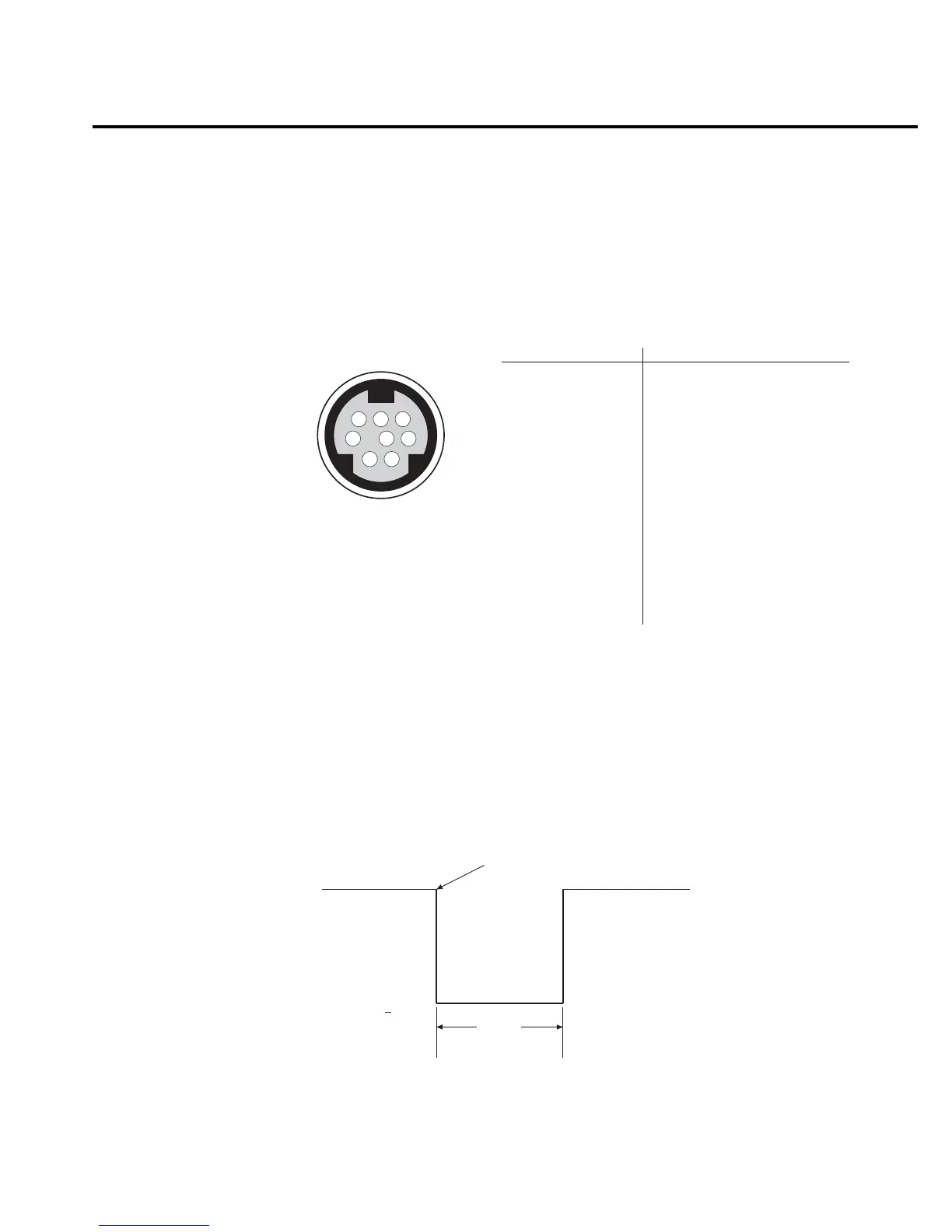
Input and output triggers are received and sent via the rear panel TRIGGER LINK connector.
The trigger link has six lines. At the factory, line #2 is selected for output triggers and line #1 is
selected for input triggers. These input/output assignments can be changed as previously
explained in this section. The connector pinout is shown in Figure 9-4.
Input trigger requirements
An input trigger is used to satisfy event detection for a trigger model layer that is using the
TLINK control source. The input requires a falling-edge, TTL compatible pulse with the speci-
fications shown in Figure 9-5.
876
54
3
21
Rear Panel Pinout Pin Number
Description
1
2
3
4
5
6
7
8
Trigger Link 1
Trigger Link 2
Trigger Link 3
Trigger Link 4
Trigger Link 5
Trigger Link 6
Ground
Ground
Trigger Link
Figure 9-4
Trigger link connection
operation
Triggers on
Leading Edge
TTL High
(2V-5V)
TTL Low
(
<0.8V)
10µs
Minimum
Figure 9-5
Trigger link input
pulse specifications

 Loading...


