18-14 Performance Verification
7. Verify current measurement accuracy for each of the currents listed in Table 18-4. For
each test point:
• Make connections to the indicated calibration standard resistor.
• Select the correct Model 6514 measurement range.
• Calculate the actual required calibrator voltage: V = IR, where I is the desired applied
current, and R is the actual standard resistor value.
• Set the calibrator to the calculated voltage.
•Verify that Model 6514 current reading is within the reading limits listed in the table.
8. Repeat the procedure for negative source currents with the same magnitudes as those
listed in Table 18-4.
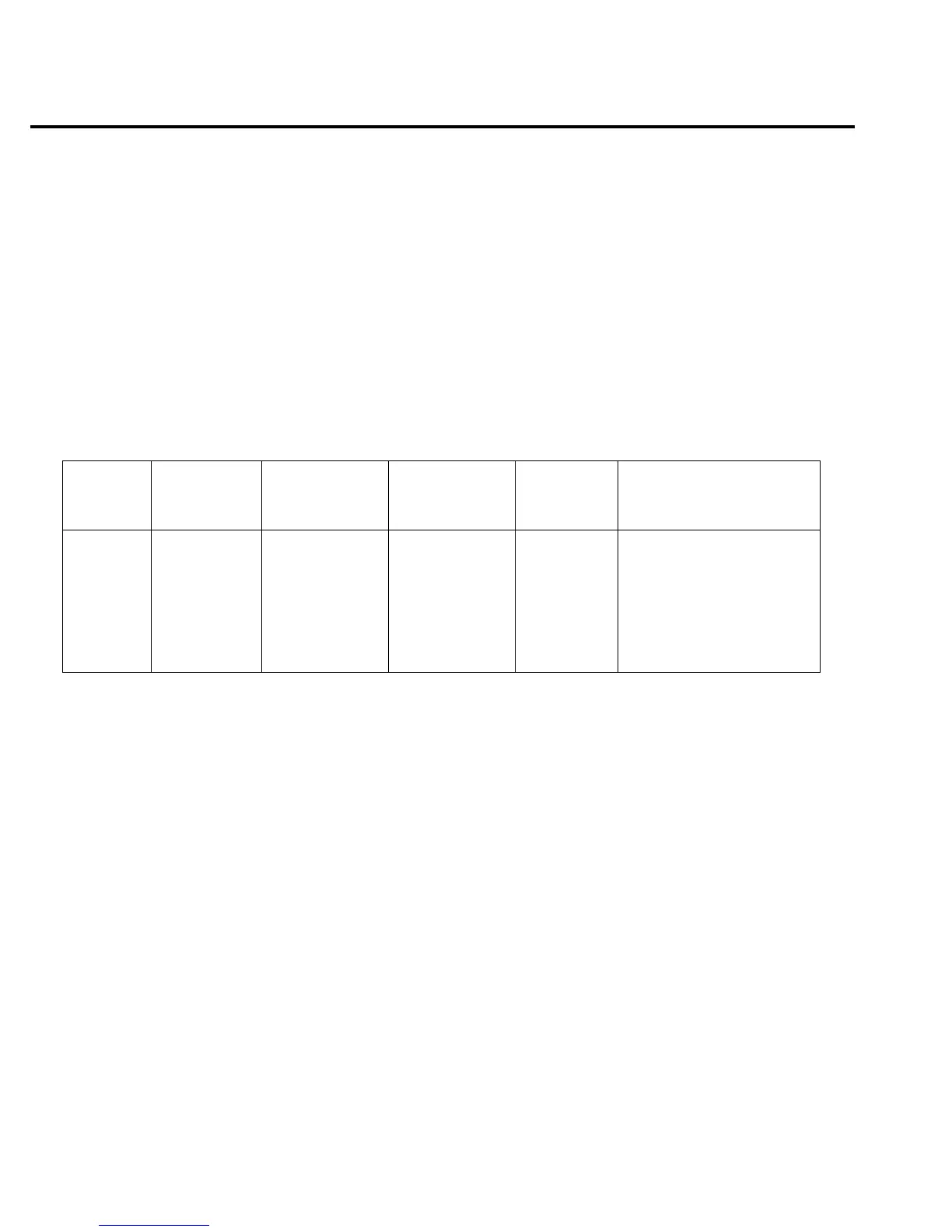
Table 18-4
20pA-2µA range current measurement accuracy reading limits
Model
6514 range
Nominal
calibrator
voltage
Calibration
standard
resistor
1
Applied current
Actual
voltage
2
Model 6514 amps reading
limits (1 Year, 18˚C-28˚C)
20pA 2V 100GΩ 20.0000pA ______V 19.7970 to 20.2030pA
200pA 2V 10GΩ 200.000pA ______V 197.995 to 202.005pA
2nA 2V 1GΩ 2.00000nA ______V 1.99570 to 2.00430nA
20nA 2V 100MΩ 20.0000nA ______V 19.9595 to 20.0405nA
200nA 20V 100MΩ 200.000nA ______V 199.595 to 200.405nA
2µA 200V 100MΩ 2.00000µA ______V 1.99790 to 2.00210µA
1
Nominal resistance values shown. Use actual characterized value for calculations.
2
Calculate actual calibrator voltage as follows: V = IR, where I is desired applied current, and R is actual standard resistance value.

 Loading...


