Remote Operation 12-19
Error messages
See Appendix B for RS-232 error messages.
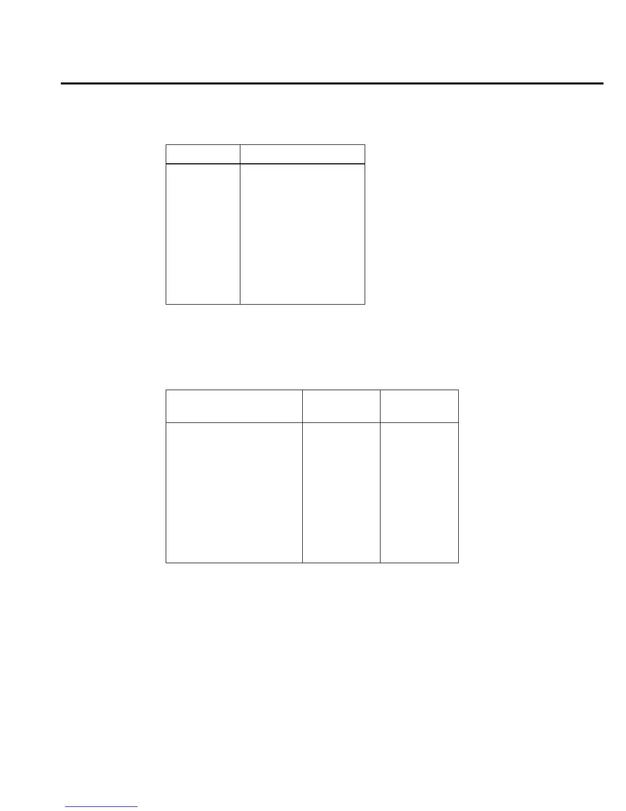
Table 12-2
RS-232 connector pinout
Pin number Description
1 DCD, data carrier detect
2 TXD, transmit data
3 RXD, receive data
4 DTR, data terminal ready
5 GND, signal ground
6 DSR, data set ready
7 RTS, ready to send
8 CTS, clear to send
9 No connections
RTS and CTS are tied together.
DCD, DTR, and DSR are tied together.
Table 12-3
PC serial port pinout
Signal
DB-9
pin number
DB-25
pin number
DCD, data carrier detect 1 8
RXD, receive data 2 3
TXD, transmit data 3 2
DTR, data terminal ready 4 20
GND, signal ground 5 7
DSR, data set ready 6 6
RTS, request to send 7 4
CTS, clear to send 8 5
RI, ring indicator 9 22