Digital I/O, Analog Outputs, and External Feedback 11-3
NOTE Information on using the digital I/O to control a component handler for limit tests is
provided in Section 10.
• External device control — Each digital output can be used as a control switch for an
external device (i.e. relay) circuit. Each output line can sink up to 500mA. Drive voltage
is provided by an external source (+5V to +33V).
• Logic Control — The four digital outputs can be used as inputs to logic devices.
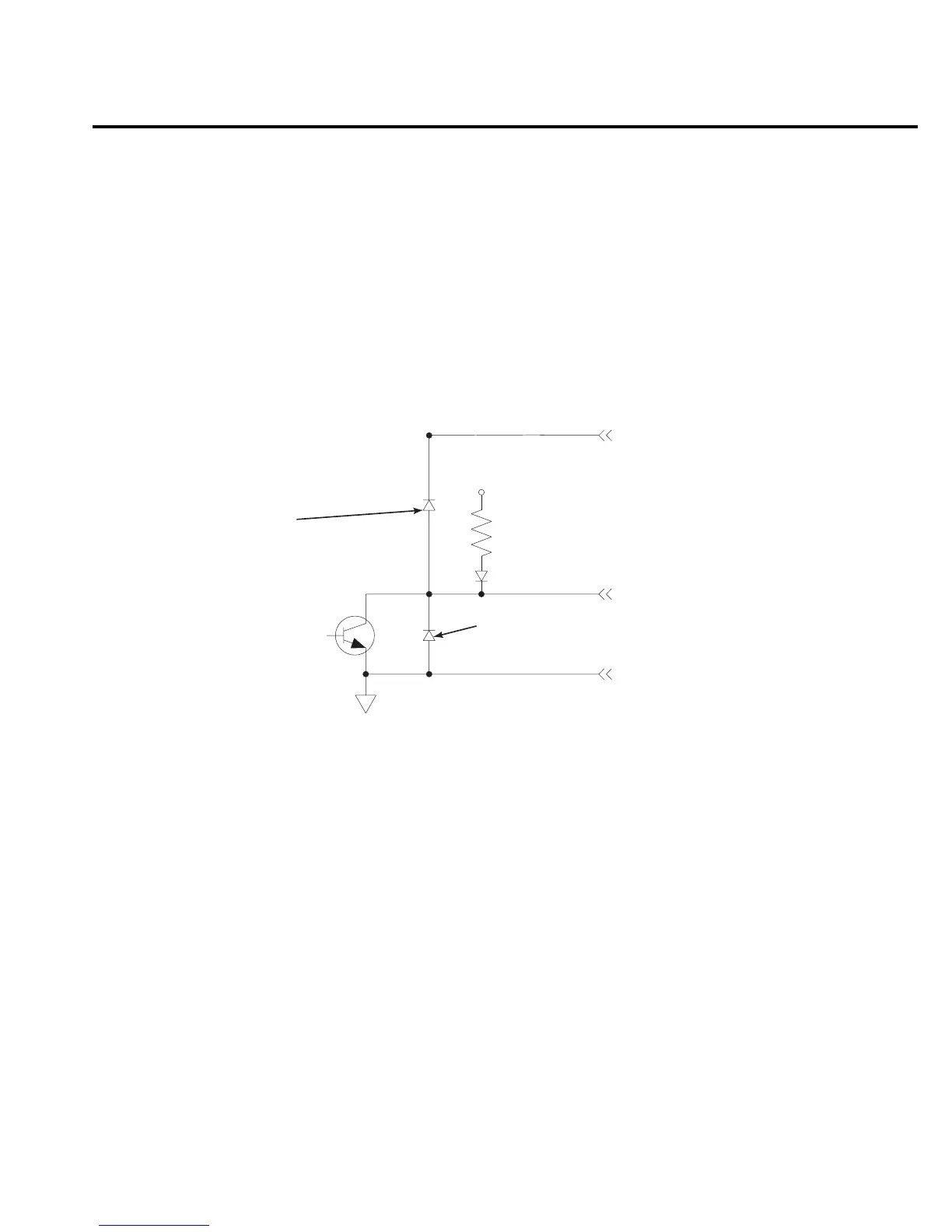
The simplified schematic for the digital outputs are shown in Figure 11-2. Note that this illus-
tration shows the schematic for one digital output. All four digital output circuits are identical.
Sink mode — controlling external devices
Each output can be operated from an external supply (voltage range from +5V to +33V
applied through the external device being driven). The high current sink capacity of the output
driver allows direct control of relays, solenoids, and lamps (no additional circuitry needed).
As shown in Figure 11-2, each of the four digital, open-collector outputs includes a built-in
pull up resistor to +5V. The output transistor is capable of sinking 500mA from voltages up to
+33V. Each output channel contains a fly-back diode for protection when switching inductive
loads (such as a low power solenoid or relay coils). To use these fly-back diodes, connect the
external supply voltage to pin 5 of the digital I/O port. Make sure the external supply voltage is
between +5V and +33V and the current required by the device does not exceed 500mA.
+5V
1kΩ (Pull-up)
Pin 9 - Digital Ground
Digital Output
Pin 5 - External Voltage Flyback
connection (+5V to +33V)
Digital Output
Flyback Diode
Protection
Diode
Figure 11-2
Digital I/O port
simplified
schematic