5-4 Coulombs Measurements
Step 6 Connect the charge to be measured to the electrometer
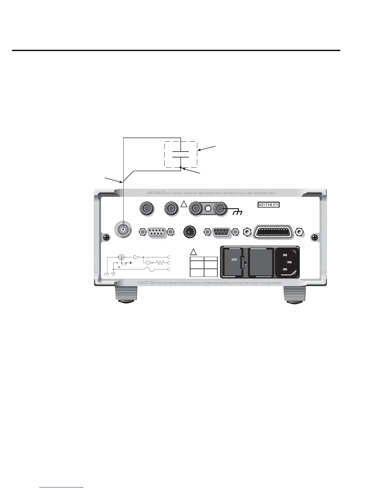
Basic connections for amps measurements are shown in Figure 5-1.
NOTE See “Connection Basics” in Section 2 for fundamental information on making con-
nections to the electrometer input.
Step 7 Take the charge reading from the display
If using auto discharge, use the REL key to zero the display when the integrator resets.
Remember that Rel was enabled in Step 5. Therefore, you will have to press REL twice. The first
press disables Rel, and the second press re-enables it to zero the display. See “Auto Discharge
Hop” in “Coulombs Measurement Considerations” (in this section).
Black (LO)
Red (HI)
237-ALG-2
Cable
Metal Noise Shield
(Optional)
6514 Rear Panel
Input LO connected
to shield
RS232DIGITAL I/O
PREAMP OUT
250V PK
2V ANALOG
OUTPUT
COMMON CHASSIS
120
FUSE LINE
630mA
LINE RATING
50, 60Hz
60 VA MAX
T
(SB)
100 VAC
120 VAC
315mAT
(SB)
220 VAC
240 VAC
INPUT 250V PK
IEEE-488
(CHANGE IEEE ADDRESS
WITH FRONT PANEL MENU)
TRIGGER LINK
!
!
MADE IN
U.S.A.
V, GUARD
(PROGRAMMABLE)
OFF
ON
GUARD
(FOLLOWS
INPUT)
(INTERNAL)
INPUT PREAMP
10K
PREAMP
OUT
2V ANALOG
OUTPUT
COM
Figure 5-1
Typical connections
for coulombs

 Loading...


