12-18 Limit Testing 2400 Series SourceMeter
®
User’s Manual
Auto-clear timing
The following timing diagram example (Figure 12-9) and discussion explain the relation-
ship between the digital output lines for auto-clear.
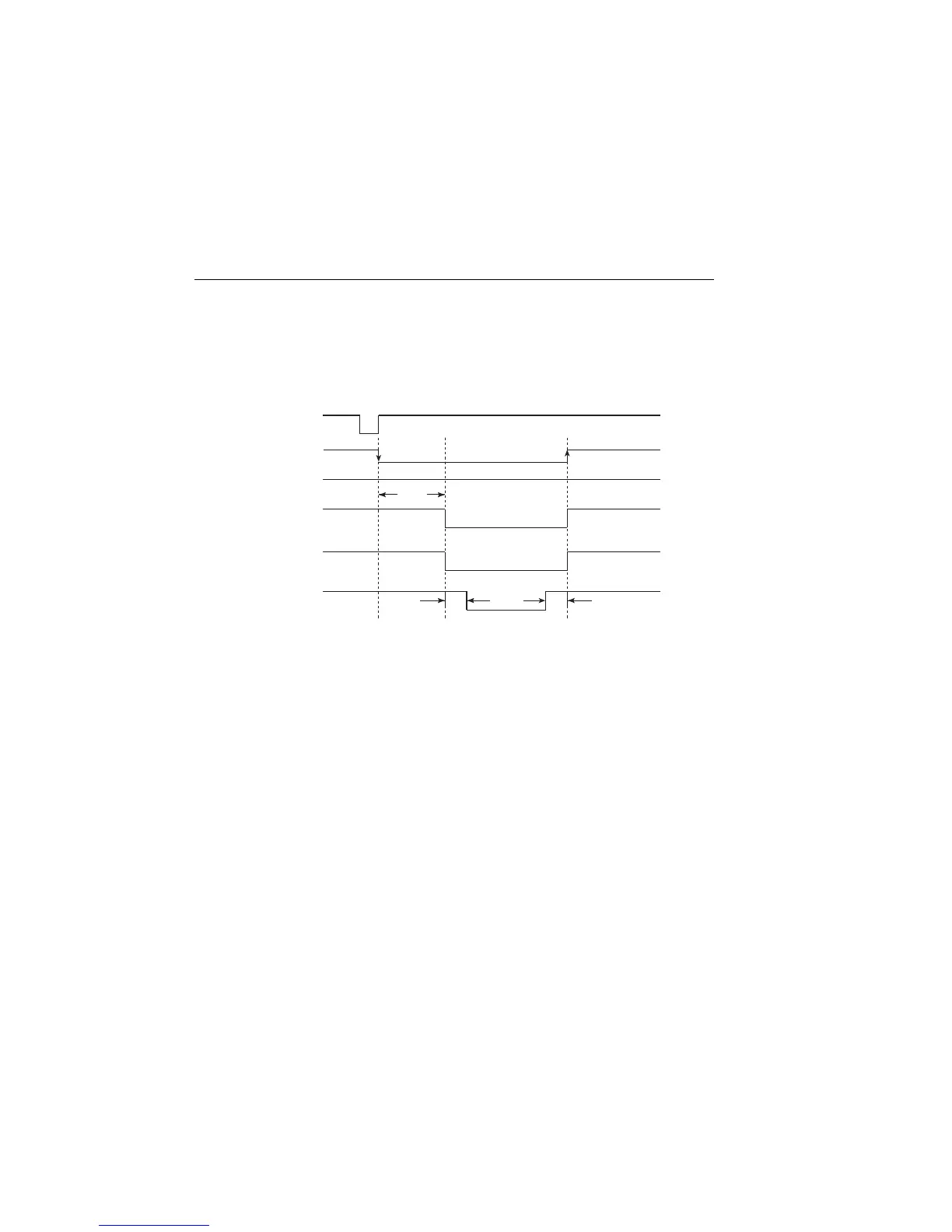
Figure 12-9
Digital output auto-clear timing example
Initially, the four digital output lines are cleared (in this case, they are all set high). Limit
tests start when the start-of-test (SOT) pulse is received from the component handler.
When the testing process is finished, the pass or fail pattern is applied to the digital output.
As shown in the diagram, lines 2, 3, and 4 go low while line 1 remains high.
The pulse width (delay) of the pass/fail pattern can be set from 0 to 60sec (10µsec resolu-
tion) as required by the component handler. Note that the delay specifies the pulse width
of line 4. The pulse width of lines 1, 2, and 3 is actually 20µsec longer. Line 4 is skewed
because it is used as the end-of-test (EOT) strobe by category register component han-
dlers. Lines 1, 2, and 3 establish the bit pattern and then 10µsec later the SOT strobe tells
the handler to read the bit pattern and perform the binning operation. This 10µsec offset is
used to make sure the correct bit pattern is read by the handler.
After the pass/fail is read by the handler, the digital output returns to the clear pattern with
auto-clear enabled.
SOT*
Line 1
Line 2
Line 3
Line 4
(EOT)
10µs10µs
Delay
/BUSY
Meas.
* With the SOT line being pulsed low (as shown),
↓STEST must be the selected
event for the trigger model. If the SOT line is instead pulsed high by the handler,
↑STEST must be the selected arm event. For high or low pulses, select
↑↓STEST.
Artisan Technology Group - Quality Instrumentation ... Guaranteed | (888) 88-SOURCE | www.artisantg.com

 Loading...