14-20 Remote Operations 2400 Series SourceMeter
®
User’s Manual
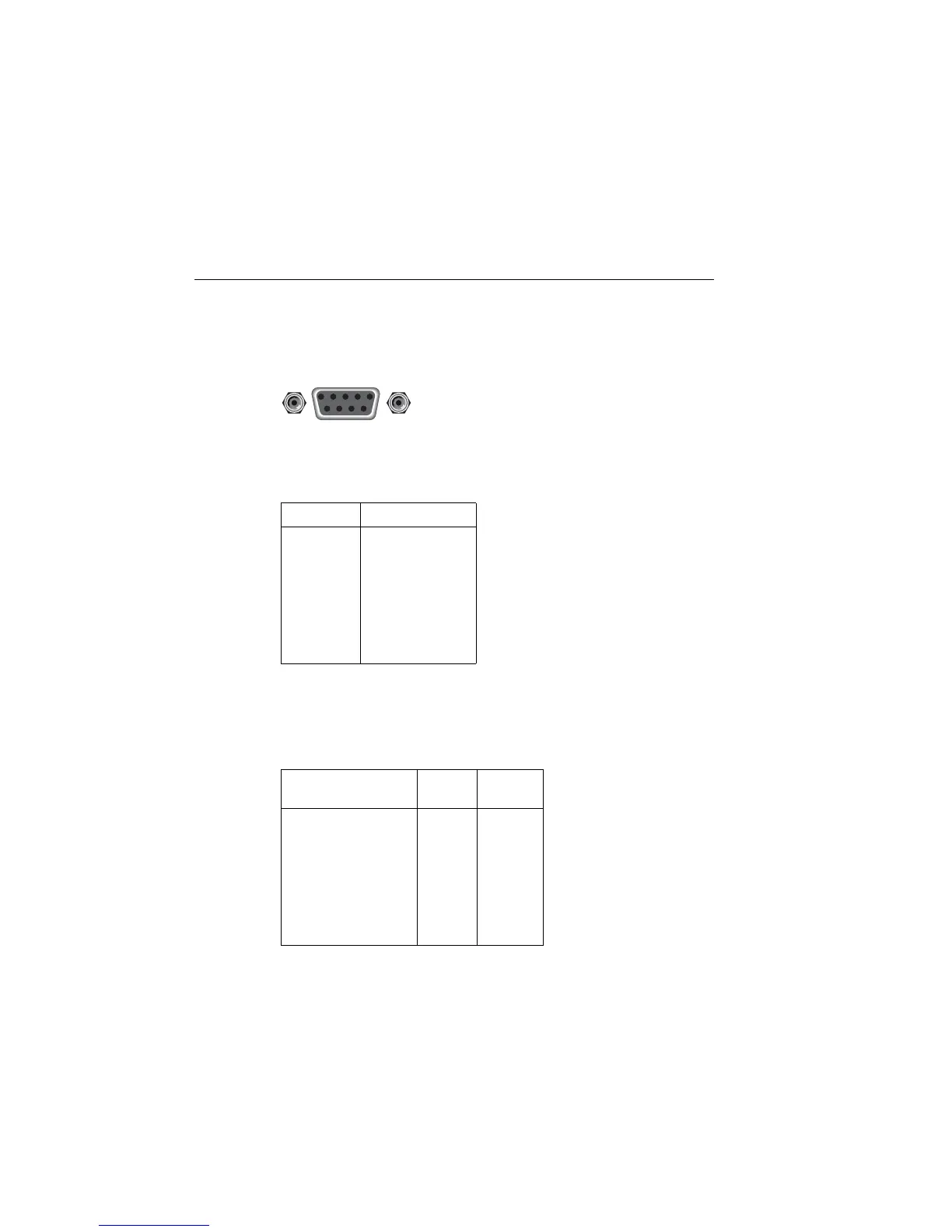
Figure 14-4
RS-232 interface connector
Table 14-3 provides pinout identification for the 9-pin (DB-9) or 25-pin (DB-25) serial
port connector on the computer (PC).
Table 14-2
RS-232 connector pinout
Pin number Description
1
2
3
4
5
6
7
8
9
Not used
TXD, transmit data
RXD, receive data
Not used
GND, signal ground
Not used
RTS, ready to send
CTS, clear to send
Not used
NOTE: CTA and RTS are tied together.
Table 14-3
PC serial port pinout
Signal
DB-9 pin
number
DB-25 pin
number
DCD, data carrier detect
RXD, receive data
TXD, transmit data
DTR, data terminal ready
GND, signal ground
DSR, data set ready
RTS, request to send
CTS, clear to send
RI, ring indicator
1
2
3
4
5
6
7
8
9
8
3
2
20
7
6
4
5
22
9876
54321
Rear Panel Connector
RS232
Artisan Technology Group - Quality Instrumentation ... Guaranteed | (888) 88-SOURCE | www.artisantg.com

 Loading...