2400 Series SourceMeter
®
User’s Manual Digital I/O Port, Safety Interlock, and Output Configuration 13-3
SOT line
The input line (SOT) is used by the handler to start limit testing. With the ↓STEST arm
event selected (Section 11, “Configuring triggering”), the handler must pulse SOT low in
order to provide event detection which starts the testing process. With the ↑STEST arm
event selected, the handler must pulse SOT high in order to provide event detection, which
starts the testing process. With ↑↓STEST selected, either a high or low SOT pulse starts
the testing process.
Interlock line
The interlock line is intended for use with a safety interlock on a device handler or test fix-
ture. See “Safety interlock,” page 13-5, for more details.
+5V output
The Digital I/O Port provides a +5V output that can be used to drive external logic cir-
cuitry. Maximum current output for this line is 300mA. This line is protected by a self-
resetting fuse (one hour recovery time).
Digital output configuration
There are two basic methods to connect external components to the digital output lines,
sink operation and source operation.
Sink operation
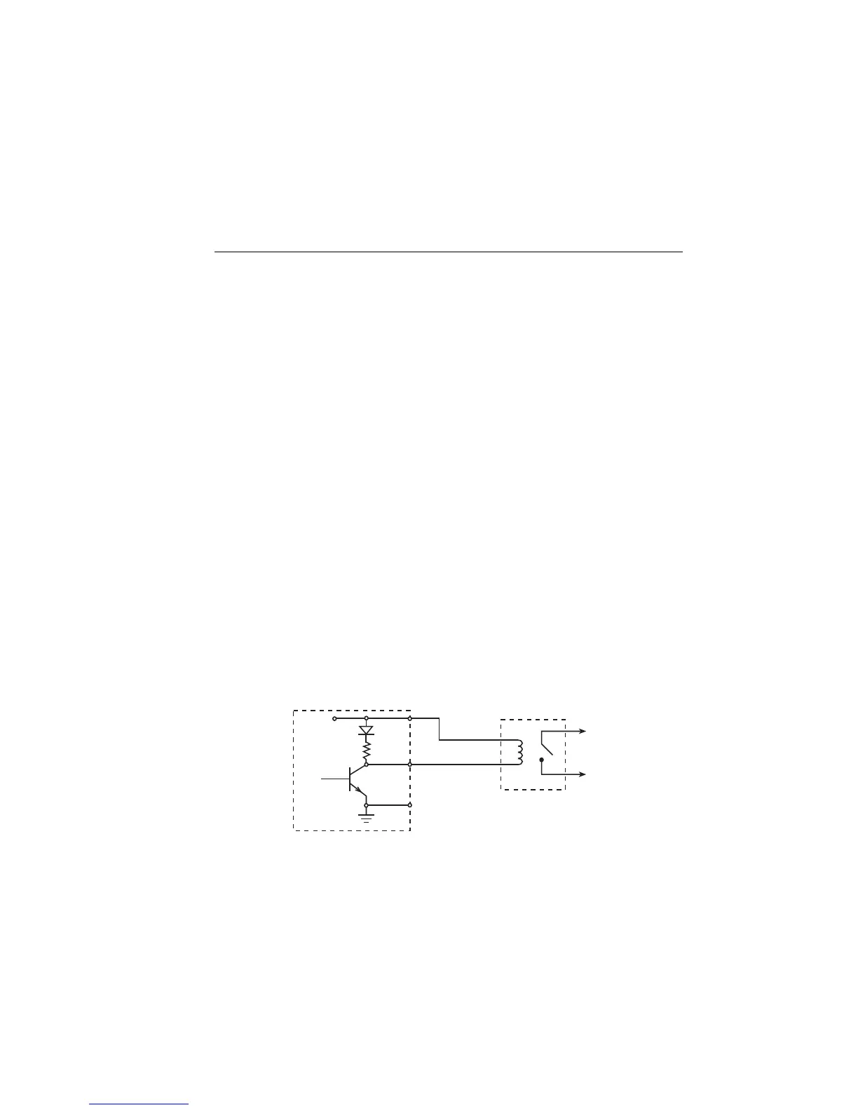
Figure 13-2 shows the basic output configuration for sink operation. Note that the external
relay coil is connected between the digital output line (pins 1 to 4) and +5V (pin 7). With
this configuration, the digital output line must be set LO to energize the relay, and the
maximum sink current is 500mA.
Figure 13-2
Sink operation
SourceMeter External
Relay
To other
Circuits
+5V
Maximum sink current: 500mA
Pins 1-4
Pin 9
Digital I/O
Port
Pin 7
Artisan Technology Group - Quality Instrumentation ... Guaranteed | (888) 88-SOURCE | www.artisantg.com

 Loading...