SERVICE
To replace a relay:
1. Remove one screw (10, Figure 3-6) holding the
crossbar in place and loosen the other screw.
2. Swing crossbar away.
3. Gently wiggle and pull upward to remove relay
(11).
4. Line up tabs and install new relay.
5. Place crossbar in original position and install
screw (10) that was removed and tighten both
screws.
To replace a circuit breaker:
NOTE: Always replace a circuit breaker with one of
the same amperage capacity as the one being
removed.
1. Place battery disconnect switch in the “OFF”
position.
2. Unplug all wiring harness(es) from relay board.
Remove four relay mounting screws and
remove relay board from truck.
3. Remove four hold down screws (3) (one in
each corner) in circuit breaker cover plate and
all circuit breaker screws. Remove cover plate
from circuit breakers.
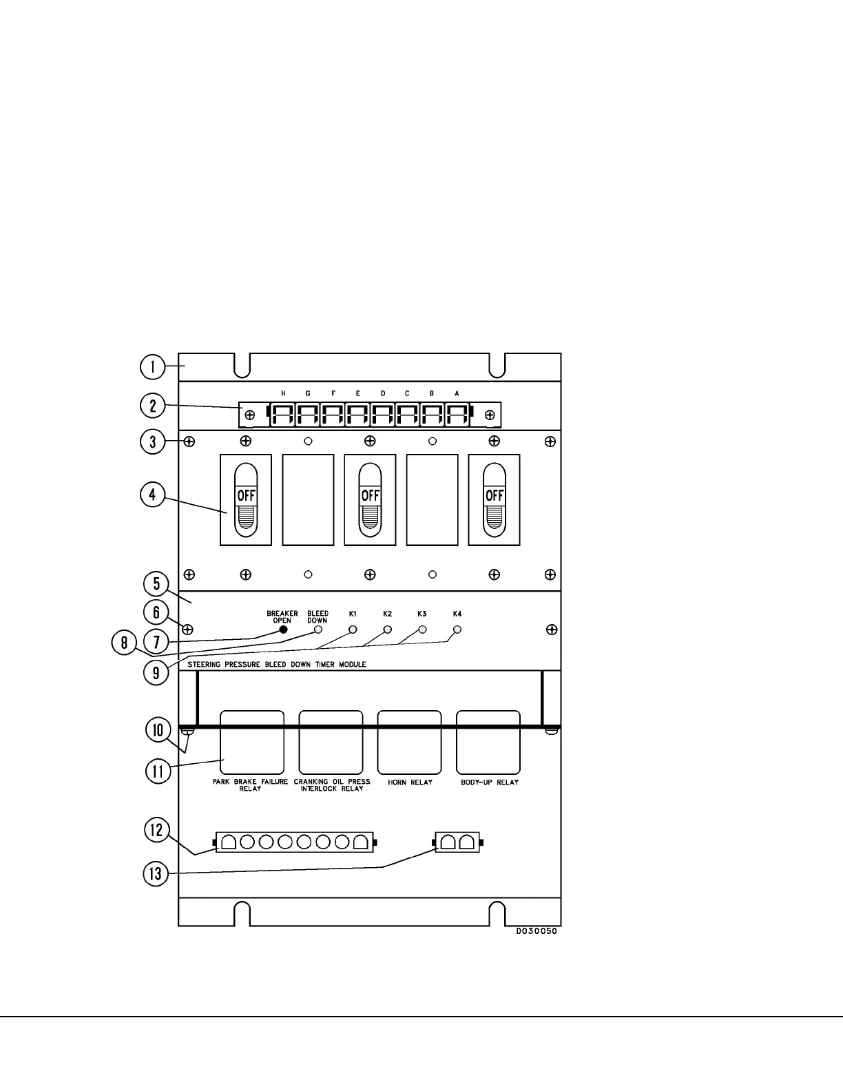
FIGURE 3-6. TYPICAL RELAY BOARD
1. Relay Board
2. Main Harness Connector
3. Screw
4. Circuit Breaker
5. Circuit Panel Card
6. Screw
7. Breaker Open Light (RED)
8. Bleed Down Light
(GREEN)
9. K1, K2, K3, K4 Lights
(GREEN)
10. Screw
11. Relay
12. Harness Connector
13. Harness Connector
 Loading...


