EasyManuals Logo
Home>Komatsu>Trucks>830E

Komatsu 830E User Manual

Komatsu 830E
783 pages
To Next Page IconTo Next Page
To Previous Page IconTo Previous Page
Page #407 background imageLoading...
Page #407 background image
L02027 Hydraulic System L2-1
HYDRAULIC SYSTEM
HYDRAULIC SYSTEM OPERATION
The following describes the basic hydraulic system
operation. Further system description is outlined
under different system circuits such as the hoist cir-
cuit and steering circuit in this section of the manual.
Refer to Section “J” for details regarding the hydrau-
lic brake system.
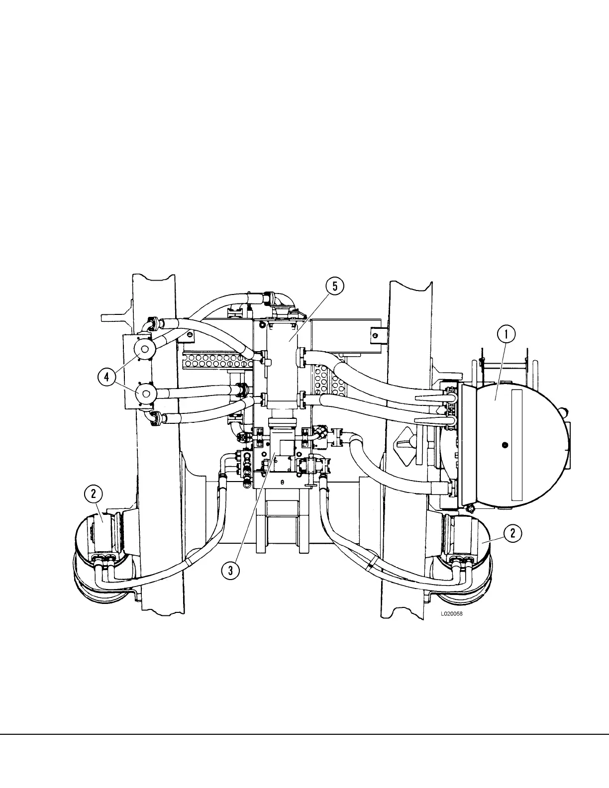
The hoist, steering and brake circuits share a com-
mon hydraulic tank (1, Figure 2-1). The tank is
located on the left frame rail forward of the rear
wheels.
The service capacity of the tank is 238 gal. (901 l).
Type C-4 hydraulic oil is recommended for use in
the hydraulic system.
NOTE: It is recommended that any hydraulic oil
to be used for filling or adding to the hydraulic
system is routed through a 3 micron filter device
prior to use.
FIGURE 2-1. HYDRAULIC PUMPS AND TANK (VIEWED FROM BELOW TRUCK)
1. Hydraulic Tank
2. Hoist Cylinder
3. Steering / Brake Pump
4. Hoist Circuit Filters
5. Hoist Circuit Hydraulic
Pump

Table of Contents

Other manuals for Komatsu 830E

Questions and Answers:

Question and Answer IconNeed help?

Do you have a question about the Komatsu 830E and is the answer not in the manual?

Komatsu 830E Specifications

General IconGeneral
BrandKomatsu
Model830E
CategoryTrucks
LanguageEnglish

Related product manuals