DIFFERENTIAL PRESSURE SWITCH
The differential pressure switch (1, Figure 3-9)
mounted on the brake valve detects an imbalance in
brake apply pressure between the front and rear brake
circuits. If the pressures differ more than shown in
Table I, "Differential Pressure Switch Test", the switch
(3) activates a warning horn and lamp in the cab to
alert the operator to a potential brake system problem.
Disassembly
1. Remove the four socket head capscrews attach-
ing the differential pressure switch body (1, Figure
3-9) to the valve body (2).
2. Remove switch assembly (3) and O-ring (12).
3. Remove plugs (5, 6 & 11).
4. Insert a hex wrench through bottom port and
remove screw plug (7).
5. Remove spring (8) and piston (9).
6. Carefully push spool assembly (10) our of its bore.
Cleaning and Inspection.
1. Clean all metal parts with solvent and air dry.
2. Inspect spool assembly (10, Figure 3-9) for scor-
ing and other evidence of damage. Inspect spool
bore in body (4). If seals are damaged, entire
differential switch assembly should be replaced.
3. Lightly lubricate spool assembly and carefully
insert in bore. Spool must slide freely and
smoothly in bore. If there is binding, the entire
differential pressure switch assembly must be
replaced.
4. Lubricate piston (9) and insert in its bore. Piston
must move freely with no binding.
5. Inspect spring (8) for cracks, distortion, etc.
6. Attach an ohmmeter to switch assembly (3) center
terminal and switch body. Actuate the switch
plunger to verify contacts close when plunger is
depressed and contacts open when released.
Plunger must operate freely in switch body.
Assembly
1. Install plug (11, Figure 3-9). Tighten plug to 190-
210 in. lbs. (21.5 - 23.7 N.m) torque.
2. Lightly lubricate Glyde rings on spool assembly
(10) and carefully insert in body (4) until it bottoms
on plug (11).
3. Install plug (5). Tighten plug to 190-210 in. lbs.
(21.5 - 23.7 N.m) torque.
4. Using new O-ring (12), install switch assembly (3).
Tighten to 55 - 60 in. lbs. (6.2 - 6.8 N.m) torque.
NOTE : In the following assembly, make a note of the
color (red or green) of spring (8). The spring color will
determine final adjustment of the switch. Refer to
Table I, "Differential Pressure Switch Adjustment".
In addition, for future service reference, the
outside of
the valve should be marked to indicate the color (red
or green) of spring (8).
5. Turn valve over and install piston (9), spring (8)
and screw plug (7). Plug should be inserted ap-
proximately 0.5 in. (13 mm) below edge of body.
Temporarily install plug (6) in screw plug port.
NOTE : The adjustment of screw plug (7) controls the
switch actuation point. Refer to “Valve Bench Test and
Adjustment, Differential Pressure Switch Adjustment ”
for calibration procedure.
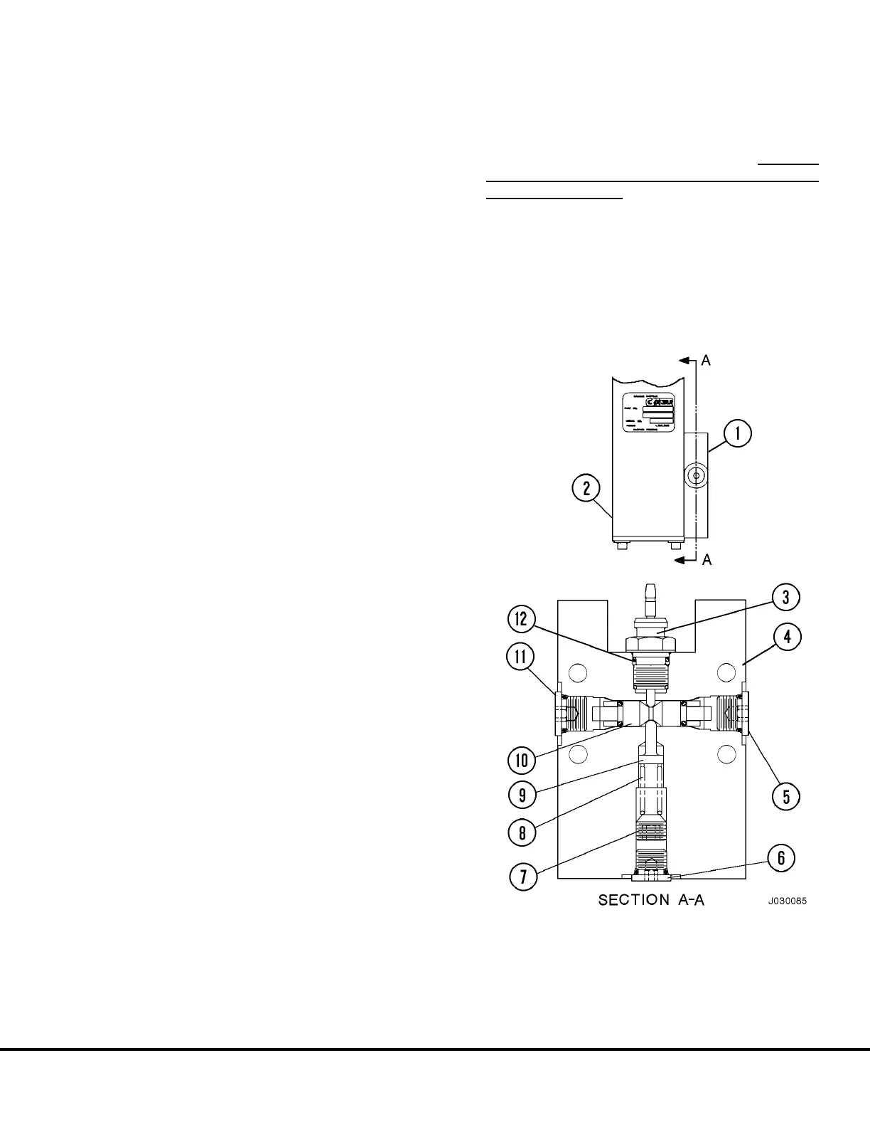
FIGURE 3-9. DIFFERENTIAL PRESSURE SWITCH
1. Differential Pressure
Switch Assembly
2. Valve Body
3. Switch Assembly
4. Body
5. Plug
6. Plug
7. Screw Plug
8. Spring
9. Piston
10. Spool Assembly
11. Plug
12. O-Ring
J03022 1/99 Brake Circuit Component Service J3-9
 Loading...


