E03012 2/02 Statex III Electrical Checkout Procedure E3-11
NOTE: PTU abbreviations shown with a line above and below after the following steps indicate
highlighted items to be observed on PTU display screen. Highlighted items will be preceded by an
“equals” sign to indicate a digital input is “true” and a digital output is “ON”. Steps 1.3, and 1.4 may
also be checked using the ACCELERATE STATE LOGIC SCREEN and step 1.5 may be checked
using the RETARD STATE LOGIC SCREEN if desired. If used, exit back to the Normal
Operation Menu and select MONITOR REAL TIME DATA SCREEN when performing step 1.6
and the remaining sequence checks.
1.3 Reverser and Propulsion Contactors Check
NOTE: When the Selector Switch is moved to change the Reverser from REVERSE to
FORWARD or NEUTRAL, FOR on the PTU display will be highlighted for a brief moment. If the
Selector Switch is moved to change the Reverser from FORWARD or NEUTRAL to REVERSE,
REV on the PTU display will be highlighted for a brief moment. This occurs very quickly and may
not be visible on some PTU's. (The FOR and REV signals are used to momentarily energize the
Reverser solenoids when a directional change is requested.)
1. Move Selector Switch to NEUTRAL. Turn key switch and control power switch to On position.
2. Verify that Reverser either remains in or shifts to forward position (to the right).
a. Verify the feedback signal:
FORFB
3. Depress throttle. No contactors should pick up. Release throttle.
4. Move Selector Switch to FORWARD.
FORIN
5. Verify that Reverser remains in forward position (to the right).
a. Verify the feedback signal:
FORFB
6. Depress throttle until AS contact is closed, and propulsion contactors MF, P1/(P2), GF, and
GFR are picked up in this sequence.
AS MF P1 (P2) GF GFR
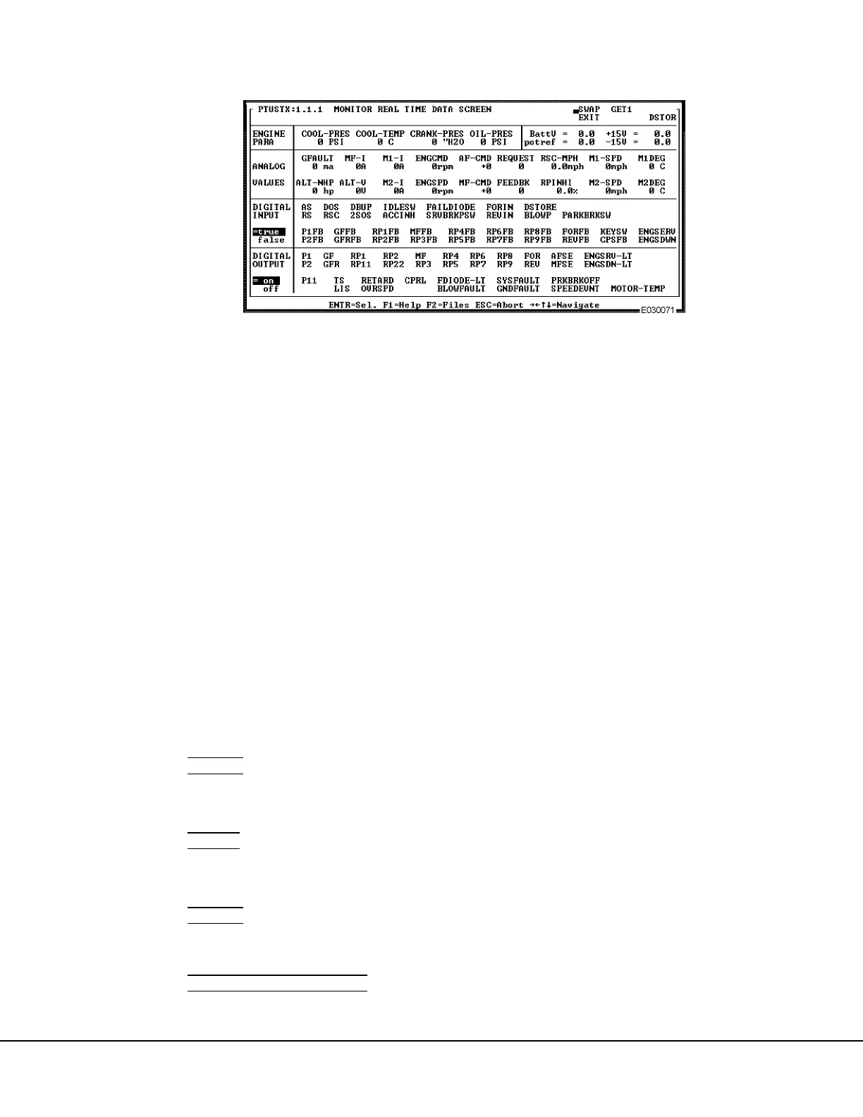
FIGURE 3-8. MONITOR REAL TIME DATA SCREEN
 Loading...


