b. Screw heating element into cartridge and
tighten securely to insure against leaks.
2. Connect the electrical leads.
3. Slide element cover into position and secure with
screws.
4. Open shut-off valves.
5. Plug in the external power source. After allowing
time for the element to warm up, outlet hoses
should feel warm to the touch.
6. Check for leaks and proper coolant level.
THERMOSTAT
Removal
1. Disconnect the external power source at the plug
in receptacle.
NOTE: It is not necessary to remove the thermostat
assembly from the heater.
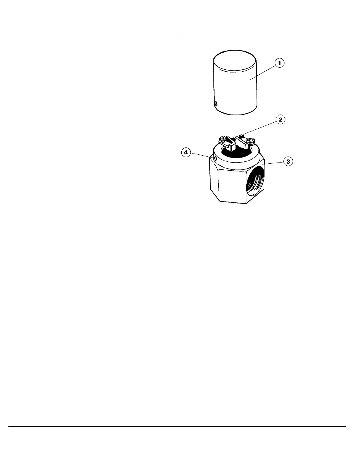
2. Remove the two screws and slide cover out of the
way.
3. Disconnect the two electrical leads.
4. Loosen the two setscrews and remove the tem-
perature sensing unit.
Installation
1. Install a new temperature sensing unit and secure
in place with two setscrews.
2. Connect the electrical leads.
3. Move cover into position and secure in place with
screws.
4. Plug in the external power source.
After allowing time for the element to warm up, outlet
hoses should feel warm to the touch.
91465
FIGURE 7-2. THERMOSTAT ASSEMBLY
1. Cover
2. Temperature Sensing
Unit
3. Housing
4. Setscrew
M7-2 Engine Coolant Heater M07001 3/95