G03018 04/03 Front Wheel Hub and Spindle G3-1
FRONT WHEEL HUB AND SPINDLE
WHEEL HUB AND SPINDLE ASSEMBLY
Removal
The following instructions will cover the complete
removal, installation, disassembly, assembly and
bearing adjustment of front wheel hub and spindle. If
only brake service is to be performed, refer to Sec-
tion "J", "Brake Circuit".
Do not loosen or disconnect any hydraulic brake
line or component until engine is stopped, key
switch is turned "Off" for 90 seconds and drain
valves on brake accumulators are opened.
For ease of handling, refer to the "Front Tire and Rim
Removal" instructions to remove front tire and rim
assembly.
1. Bleed down steering accumulator by shutting
down the engine and turn key switch "Off" for at
least 90 seconds. Open drain valves at the bot-
tom of each of the brake system accumulators.
Allow adequate time for the accumulators to
bleed down.
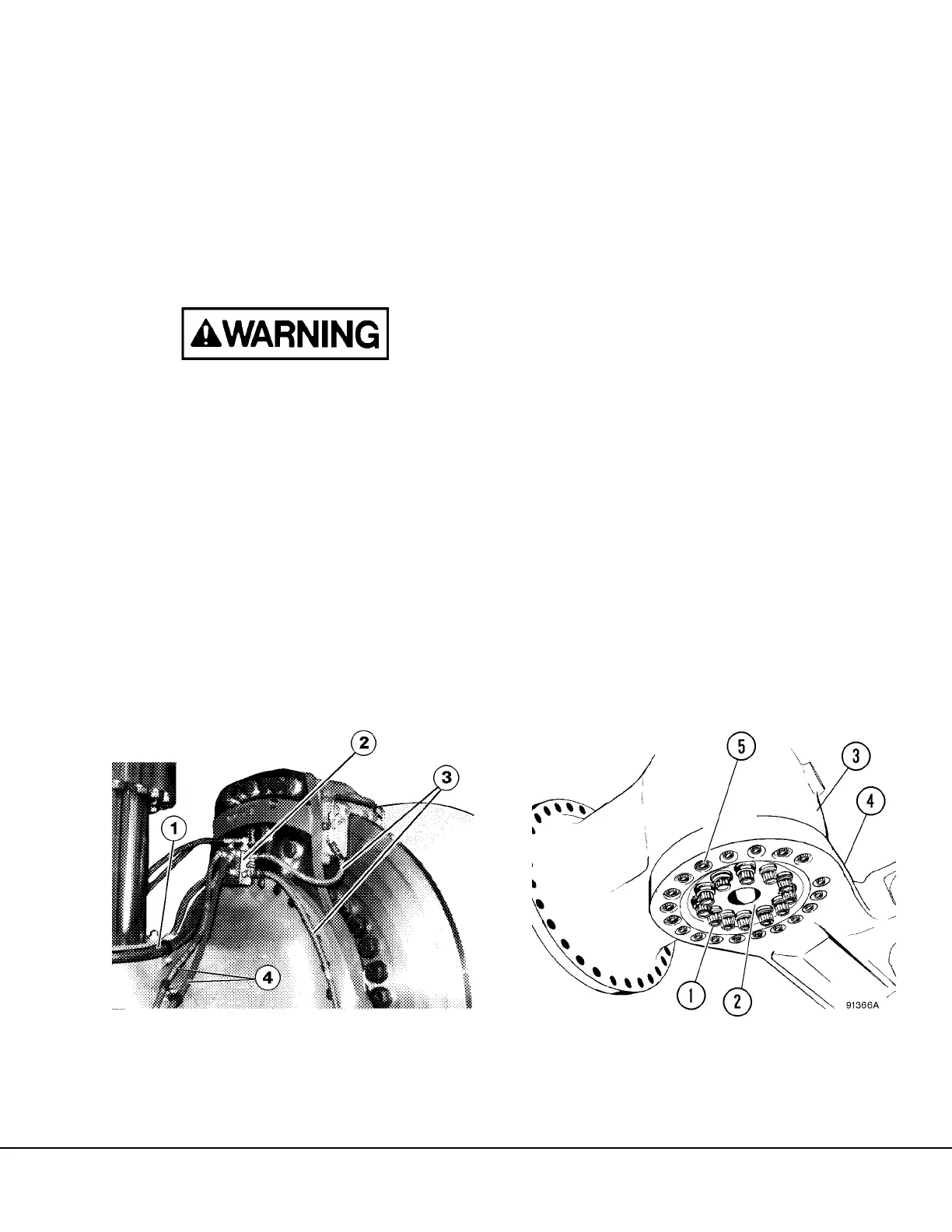
2. Disconnect brake lines leading to each caliper
and main brake supply line (1, Figure 3-1) at the
junction block. Plug or cap all lines to prevent
contamination of the hydraulic system.
3. Remove any grease lines being used for a group
lube or automatic lube system for the steering
cylinder and tie rod. Cap all lines.
4. Remove capscrews and washers securing
brake line junction block (2), and main brake
supply line (1) from spindle assembly. Plug or
cap all lines to prevent contamination of the
hydraulic system.
5. If internal work is to be performed, remove hub
drain plug (24, Figure 3-5) and allow oil to drain.
6. Remove lubrication lines from tie rod and steer-
ing cylinder. Disconnect tie rod and steering cyl-
inder rod from spindle being removed. Refer to
"Steering Cylinder and Tie Rod Removal" in this
section.
7. Position a fork lift under the wheel hub and spin-
dle assembly as shown in Figure 3-4.
8. Remove capscrews (1, Figure 3-2) securing
retainer plate (2) to spindle structure and sus-
pension. Loosen capscrews in torque incre-
ments of 500 ft. lbs. (678 N.m). Remove
retainer plate.
9. Carefully remove 13 of the steering arm cap-
screws (5) as follows:
a. Identify capscrews designated with an "X" on
the spindle pusher fabrication drawing
shown in Section "M".
b. Remove the capscrews identified in step a,
loosening them in small increments in a cir-
cular pattern.
FIGURE 3-1. BRAKE SUPPLY LINES
1. Brake Supply Line
2. Junction Block
3. Caliper Supply Lines
4. Lubrication (Grease)
Supply Lines
FIGURE 3-2. WHEEL HUB & SPINDLE REMOVAL
1. Capscrews
2. Retainer Plate
3. Spindle
4. Spindle Steering Arm
5. Retaining Capscrews
 Loading...


