G03018 04/03 Front Wheel Hub and Spindle G3-3
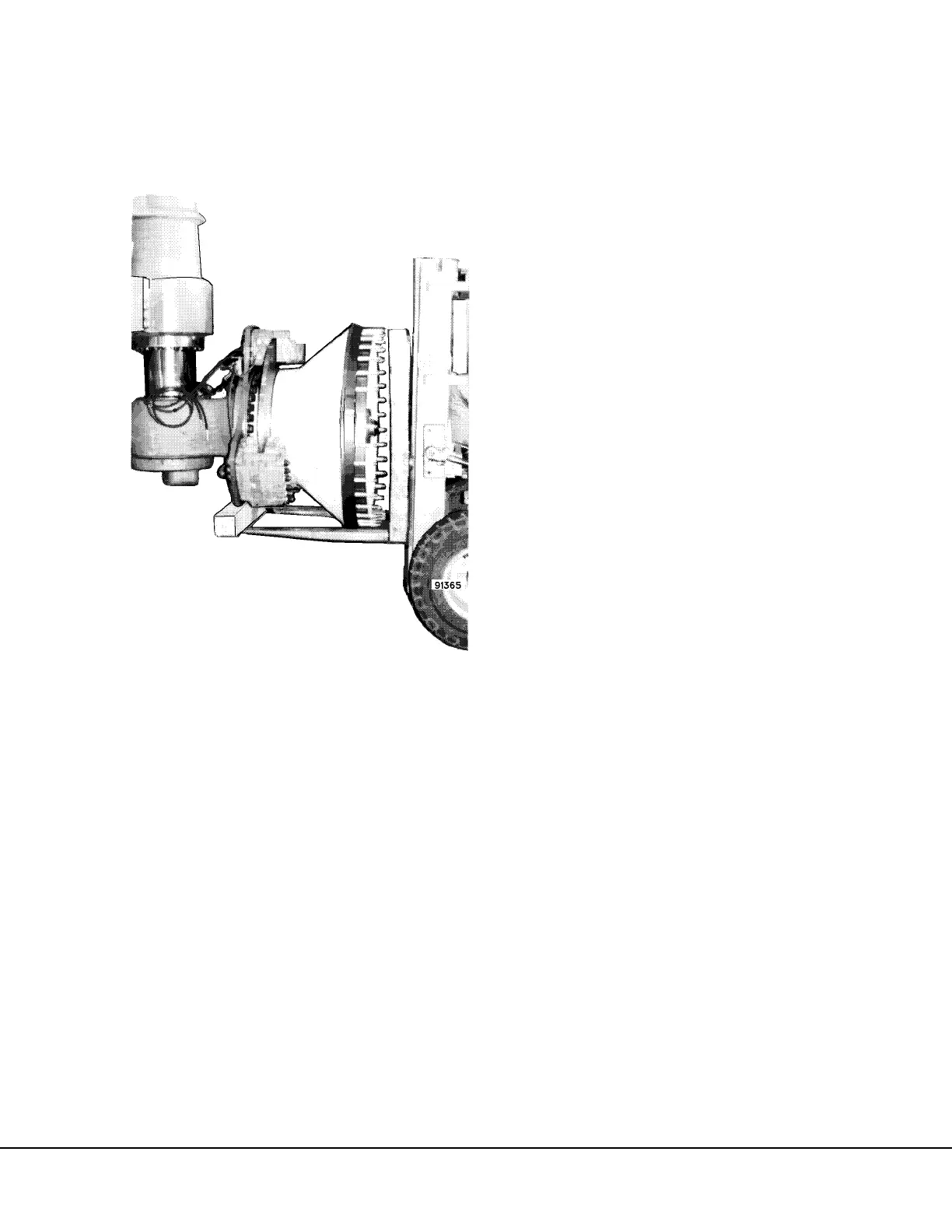
6. With a fork lift supporting the hub and spindle
assembly as shown in Figure 3-4, move to
clean work area for repair.
Installation
1. Clean spindle bore and suspension rod taper so
they are free of all rust, dirt, etc. Clean and
check the tapped holes in bottom of Hydrair®
piston for damaged threads. Retap holes, if
necessary, with 1.250 in. - 12NF tap.
2. Lubricate spindle bore and suspension rod taper
with multi-purpose grease Number 2 with 3%
Molybdenum Disulphide.
NOTE: Never use any lubricants on the spindle bore
containing copper, such as many “anti’-seize”
compounds. Products containing copper will
contribute to corrosion in this area.
3. Position spindle and wheel hub assembly on
fork lift or similar lifting device as shown in Fig-
ure 3-4.
4. Raise the spindle and wheel hub assembly into
position.
5. Secure spindle to suspension using retainer
plate (2, Figure 3-2) and capscrews (1). Tighten
capscrews using the following procedure:
a. Tighten capscrews (1) uniformly to 500 ft.
lbs. (678 N.m) torque.
b. Continue to tighten capscrews in increments
of 250 ft. lbs. (339 N.m) to obtain a final
torque of 1580 ft. lbs. (2142 N.m).
6. If removed, install steering arm (4). Clean and
check the tapped holes in bottom of spindle for
damaged threads. Retap holes, if necessary
830E, AFE 32 . . . . . . . . . .1.125 in. - 12NF tap
830E, AFE 50 . . . . . . . . . . .1.25 in. - 12NF tap
7. Install capscrews (5) and torque to:
830E, AFE 32 . . . . . . . . . . . 1430 ± 200 ft. lbs.
. . . . . . . . . . . . . . . . . . . . . . . .(1940 ± 271 N.m)
830E, AFE 50 . . . . . . . . . . . 1995 ± 100 ft. lbs.
. . . . . . . . . . . . . . . . . . . . . . . .(2705 ± 135 N.m)
8. Install steering cylinder and tie rod in their
respective mounting holes on the spindle.
Tighten retaining nuts to 525 ± 52 ft. lbs. (712 ±
71 N.m) torque. Connect lubrication lines.
9. Rotate the wheel hub to position the fill plug at
the 12 o'clock position. Remove the fill plug and
level plug. Fill wheel hub assembly at fill hole
with SAE 80W-90 oil. When properly filled, oil
should be present at the level (lower) hole.
Replace fill and level plugs.
10. Install junction block with the spacer, capscrews,
and flat washers.
11. Attach supply lines to brake calipers and connect
main supply lines to connection on frame. Bleed
brakes according to "Bleeding Brakes", Section
"J".
12. Install wheel and tires as described in "Front
Wheel and Tire Installation".
FIGURE 3-4. SPINDLE ANE WHEEL HUB
REMOVAL
 Loading...


