G02004 04/03 Tires and Rims G2-3
REAR TIRES AND RIMS
If the studs in the rear wheel motor require replace-
ment, use a special tool and tighten studs to 540
ft.lbs. (732 N.m) torque.
Removal
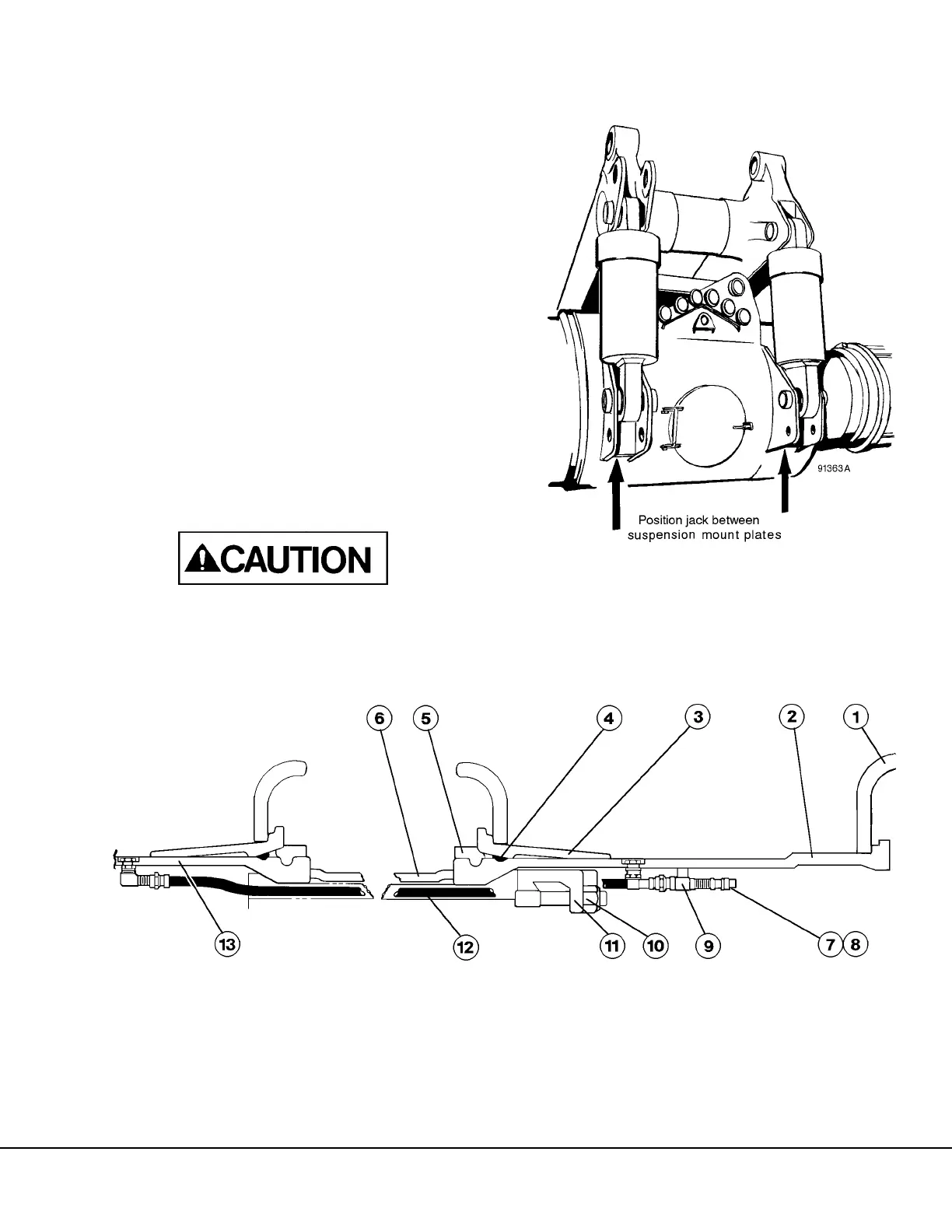
1. Park truck on level ground and block front
wheels. Position a jack in recess of rear sus-
pension mount casting as shown in Figure 2-3.
2. Raise rear axle housing of truck until tires clear
ground. Securely block up rear axle housing
near the wheel motor mounting flange.
3. Disconnect inner wheel valve stem extension
from outer wheel valve stem vinyl clamp by
loosening capscrews. Lift valve extension out of
vinyl clamp.
4. Using a tire handler (or hoist and sling if body
has been removed as shown in Figure 2-4) to
grasp outer wheel assembly. Remove wheel
nuts (10, Figure 2-4) and wedges (11) securing
outer wheel to the wheel motor hub.
Use a strap or other means, to secure inner
wheel before removing outer wheel assembly.
This will prevent the accidental slipping of inner
wheel during this operation.
FIGURE 2-3. TIRE LIFTING SLING
(BODY REMOVED)
FIGURE 2-4. REAR WHEEL ASSEMBLY
1. Side Flange
2. Outer Wheel Rim
3. Bead Seat Band
4. O-Ring
5. Lock Ring
6. Spacer
7. Valve Cap
8. Core
9. Clamp
10. Nut
11. Wheel Retainer
Wedge
12. Valve Extension Tube
13. Inner Wheel Rim
 Loading...


