L5-2 Steering Component Repair L05026
ACCUMULATOR
Removal
Relieve pressure before disconnecting hydraulic
and other lines. Tighten all connections before
applying pressure. Hydraulic fluid escaping
under pressure can have sufficient force to enter
a person's body by penetrating the skin and
cause serious injury and possibly death if proper
medical treatment by a physician familiar with
this injury is not received immediately.
1. Turn keyswitch “Off” and allow 90 seconds for
the accumulators to bleed down. Turn the
steering wheel to be certain no oil remains in
the accumulator.
2. Remove Guard (5, Figure 5-3).
Make certain only the small swivel hex nut (4,
Figure 5-2) turns. Turning the complete charging
valve assembly may result in the valve assembly
being forced out of the accumulator by the nitro-
gen pressure inside. Wear protective face mask
when discharging nitrogen gas.
3. Loosen small hex nut (4, Figure 5-2) three com-
plete turns. Remove valve cap (1). Depress the
valve stem until all nitrogen pressure has been
relieved.
4. Disconnect electrical leads at the pressure
switch located on top of the accumulator.
5. Disconnect and plug the hydraulic line (3, Figure
5-4) at the bottom of the accumulator.
6. Connect a lifting device to the top section of the
accumulator and take up slack.
The accumulator weighs approximately 310 lbs.
(140 Kg). Use a suitable lifting device that can
handle the load safely.
7. Remove the capscrews, flatwashers and lock-
nuts on the clamps (2, Figure 5-4) securing the
accumulator to the mounting bracket.
8. Lift accumulator clear of the mounting bracket
and move to a clean work area for disassembly.
9. Clean exterior of accumulator before starting
disassembly.
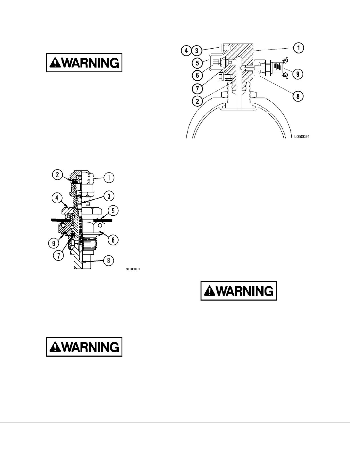
FIGURE 5-2. CHA
1. Valve Cap
2. Seal
3. Valve Core
4. Swivel Nut
(Small Hex Nut)
5. Rubber Washer
6. Valve Body
(Large Hex Nut)
7. O-Ring
8. Valve Stem
9. O-Ring
1. Valve Manifold
2. O-Ring
3. Capscrew
4. Lockwasher
5. Guard
6. Cap
7. Flat Gasket
8. Valve Assembly
9. Pressure Switch
FIGURE 5-3. ACCUMULATOR VALVES
 Loading...


