6. Install front cover, tighten nuts to 115 ft.lbs. (156
N-m) torque.
7. Pack grease in spring side of shaft seal and install
into bore of front cover.
8. Install snap ring (13).
9. Install outer seal. Pack spring side of seal before
installation.
10 After assembly is complete, 3 ft. lbs. (4 N-m)
torque should rotate shaft.
Installation
1. With a new gasket, install pump on mounting studs.
2. Tighten nuts to standard torque.
3. Pour hydraulic oil into pump.
4. Connect hoses, O-rings and split flange clamps.
Tighten outlet split flange to standard torque.
5. With suction hose loose, temporarily pressurize
the hydraulic tank with 15 psi (103 kPa) regulated
air pressure. Be sure oil is present at pump.
Tighten suction line split flange capscrews to
standard torque.
BLOWER DRIVE MOTOR
Before removing hydraulic lines from motor be
sure steering accumulators are completely bled
down. Turn steering wheel to check that accumu-
lators have bled down.
91455
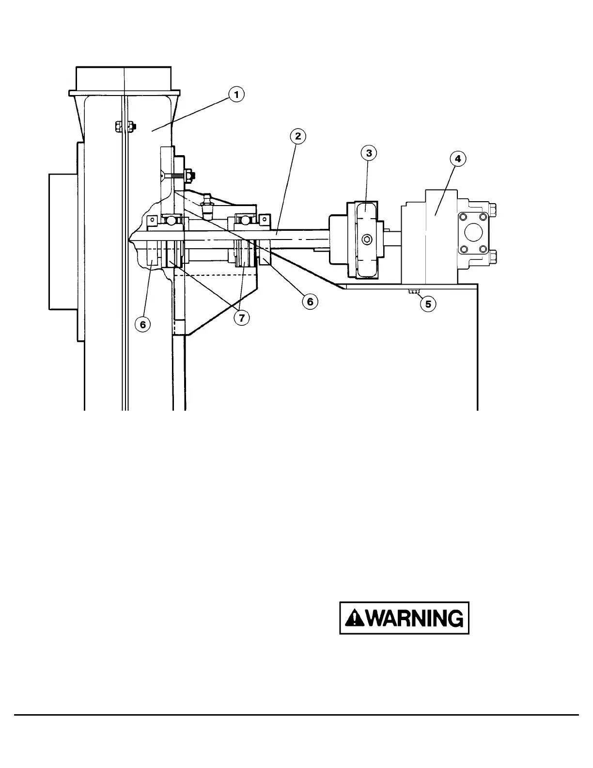
FIGURE 4-3. BLOWER AND HYDRAULIC MOTOR ASSEMBLY
1. Fan Assembly
2. Blower Shaft
3. Flex Coupling
4. Hydraulic Motor
5. Motor Mounting
Capscrews
6. Locking Collar
7. Bearings
M4-4 Alternator and Wheelmotor Cooling Air Filter System M04002 12/89
 Loading...


