HYDRAULIC BRAKE ACCUMULATORS
There are two hydraulic brake accumulators located
on the brake manifold in the brake control cabinet
behind the operator’s cab. The larger accumulator [2.5
gal. (9.51 l) capacity] supplies the pressure necessary
for actuation of the front service brakes. The small
accumulator [1 gal. (3.79 l) capactiy] supplies pressure
to activate the rear service brakes.
Accumulators maintain high pressure. DO NOT
disconnect any hydraulic line from the accumula-
tors or brake system until all hydraulic pressure
has been manually drained from accumulators.
Open manual drain valves located on the brake
manifold in the brake cabinet to drain pressurized
oil. The manual bleeddown valve for the rear accu-
mulator is identified as “NVR”. The manual bleed-
down valve for the front accumulator is identified
as “NVF”.
Brake Accumulator Bleed Down Procedure
The brake accumulators can be bled down by rotating
the manual bleeddown valves (NVR and NVF) coun-
terclockwise. The valves are located on the brake
manifold in the hydraulic brake cabinet.
1. Turn handles counterclockwise to open valves.
2. Confirm accumulators are bled down by applying
the “Brake Lock” switch (key switch “On”, engine
shut down) and applying service brake pedal. The
service brake light should not come on.
3. Close the bleeddown valves by rotating clockwise.
Removal
1. Shut down engine and exhaust all hydraulic pres-
sure from the system by opening accumulator
manual drain valves.
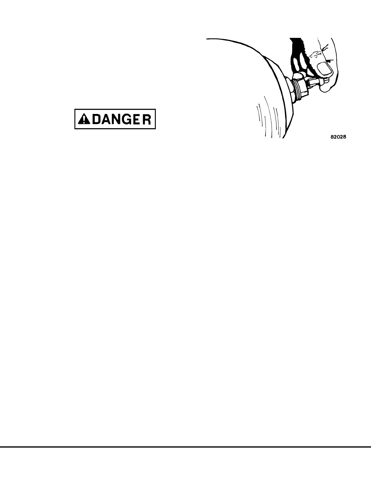
2. Remove the valve guard and “Dyna-seal” from top
of accumulators.
3. Depress valve core to release gas precharge
pressure from accumulator bladder. (Refer to Fig-
ure 3-13).
4. Remove accumulator mounting bracket. Loosen
and remove accumulator from the brake mani-
fold. Plug opening on brake manifold to prevent
contamination.
5. Transfer accumulator to work area.
Installation
1. After service repairs or bench test has been
completed, move the accumulators to the brake
control cabinet. DO NOT precharge accumula-
tors on the bench test.
2. Position the accumulators on the brake manifold.
Tighten fittings securely. Install mounting brack-
ets. Secure mounting brackets in place with cap-
screws and lockwashers. Tighten capscrews to
standard torque.
3. Refer to “Charging Procedure” in this section.
4. Replace “Dyna-seal” and valve guard on top of
accumulators.
Disassembly
1. Securely clamp accumulator (preferably in a chain
vise). Make sure accumulator shell is suitably
protected by strips of padding or soft metal on vise
base.
2. Remove core from gas valve using valve core tool.
(Refer to Figure 3-13).
3. Remove pipe plug from plug & poppet assembly.
4. Remove locknut from plug and poppet assembly
using a spanner wrench and an adjustable
wrench. One for torque and one for counter-
torque. (Refer to Figure 3-14).
5. Remove spacer, Figure 3-15.
6. With palm of hand, push plug and poppet assem-
bly into the shell.
7. Insert hand into shell and remove O-ring, washer
and anti-extrusion ring from plug. Fold anti-extru-
sion ring to enable removal. (Refer to Figure
3-16).
8. Remove plug and poppet assembly from shell.
(Refer to Figure 3-17.)
FIGURE 3-13. VALVE CORE REMOVAL
J03022 1/99 Brake Circuit Component Service J3-15
 Loading...


