BRAKE ASSEMBLIES WITH INTEGRAL
MOUNTED ELECTRONIC RETARD PEDAL
(Dual Function Pedal)
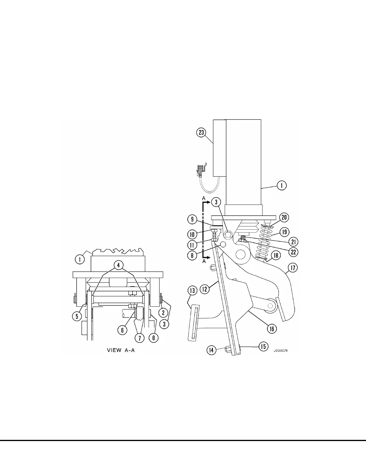
Installation of Retard Pedal To Brake Pedal
Follow “Installation Of Brake Pedal Actuator Assembly
to Brake Valve” instructions on previous page. Al-
though the brake pedal actuator structure (7, Figure
3-11 & 18, Figure 3-11) is different on each valve, the
assembly procedure is identical.
1. Install nylon bearings (7, Figure 3-12) in retard
pedal.
2. Install retard pedal (16) to brake pedal actuator
(17) with pivot shaft (8). Install two retainer clips
(6).
3. With jam nut (10) loose, adjust capscrew (11) until
roller on retard pedal just contacts the brake
pedal actuator. Tighten jam nut (10).
4. Connect wiring harness to retard pedal.
1. Brake Valve
2. Retainer Clip
3. Pivot Shaft
4. Bushings
5. Shims
6. Retainer Clip
13. Pad
14. Nut
15. Capscrew
16. Electronic Retard
Pedal Assembly
17. Brake Pedal Actuator
18. Spring Pivot (Lower)
19. Spring
20. Spring Pivot (Top)
21. Set Screw
22. Jam Nut
23. Differential Pressure Switch
7. Nylon Bearing
8. Pivot Shaft
9. Place 0.025 in. Shim Here
10. Jam Nut
11. Capscrew
12. Pedal Structure
FIGURE 3-12. BRAKE VALVE WITH RETARD PEDAL
J3-14 Brake Circuit Component Service J03022 1/99

 Loading...


