COMPONENT DESCRIPTION
HYDRAULIC TANK
The hydraulic tank supplies hydraulic oil for the
hoist, steering, and brake circuits. The tank is
located on the left hand frame rail forward of the
rear wheels. The service capacity is 238 gal. (901 l).
Refer to Section “P” for the correct type hydraulic oil
recommended for use in the hydraulic system.
Oil used in the hoist circuit flows through two 100
mesh wire suction strainers to the inlet housing of
the hoist pump. Air drawn into the tank during oper-
ation is filtered by dual air filters located on the top
of the tank. Oil level can be checked visually at sight
glasses located on the face of the tank. Oil level
should be checked periodically and be visible in the
bottom sight glass when the body is down and the
engine is running.
HOIST PUMP
The hoist pump is a tandem gear type pump driven
by an accessory drive at the rear of the traction
alternator. The pump has a total output of 240 GPM
at 1900 RPM. The hoist pump also drives the steer-
ing and brake supply pump located at the rear of the
hoist pump. Hoist pump output is directed to two
remote mounted high pressure filters. Maximum
hoist pump output pressure is 2500 psi (17.2 MPa).
HIGH PRESSURE FILTERS
Hoist pump output flows to two remote mounted
high pressure filters located on the lower inboard
side of the fuel tank. The filter elements are rated at
7 micron. The filter assembly is equipped with a
bypass valve which permits oil flow if the filter ele-
ment become plugged. Flow restriction through the
filter element is sensed by a pressure differential
switch.
This switch will turn on an over-
head panel mounted, yellow
warning light to indicate filter
service is required. The light is
labeled “Filter Monitor” and will
come on when restriction
reaches approximately 35 psi
(241 kPa). Actual filter bypass
will result when the filter ele-
ment restriction reaches
approximately 50 psi (345 kPa).
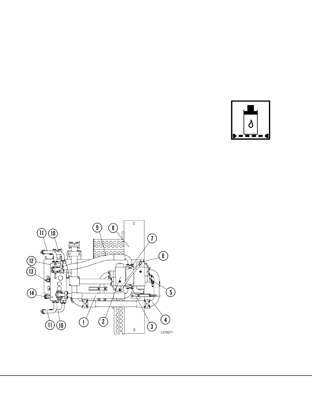
FIGURE 7-2. HOIST PUMP/VALVE MODULE
1. POWER DOWN Line
2. Hoist Valve Assembly
3. DOWN Pilot port
4. Hoist Valve Return to Tank
5. Hoist Valve Inlet from Filter
6. Supply to Pilot Valve
7. RAISE Pilot Port
8. Pump/Valve Module Mount Str.
9. POWER UP Line
10. POWER DOWN to Hoist Cylinder
11. POWER UP to Hoist Cylinder
12. Counterbalance Valve Manifold
13. Counterbalance Valve
14. APU Quick Disconnect
 Loading...


