H03015 4/03 Rear Suspensions H3-1
REAR SUSPENSIONS
The HYDRAIR
®
II suspensions are hydro-pneumatic
components containing oil and nitrogen gas. The oil
an gas in the four suspensions carry the gross truck
weight less wheels, spindles and final drive assem-
bly. The rear suspension cylinders consist of two
basic components; a suspension housing attached to
the rear axle housing, and a suspension rod attached
to the frame.
The HYDRAIR
®
II suspension cylinder requires only
normal care when handling as a unit. However, after
being disassembled these parts must be handled
carefully to prevent damage to the machined sur-
faces. Surfaces are machined to extremely close tol-
erances and are precisely fitted. All parts must be
completely clean during assembly.
Removal
NOTE: Suspension mounting pins must contain
threaded holes at the inboard end of each pin in
order to use the removal tools listed above. If the
pins do not contain the necessary holes, new pins
may be purchased, or a rework of the pins is neces-
sary. Refer to Figure 3-5 for pin rework details.
1. Remove capscrews, washers, and metal shield
(2, Figure 3-1) from the suspension.
2. Remove charging valve cap, (1, Figure 3-2)
loosen small hex (4) on charging valve and turn
counterclockwise three full turns to unseat valve
seal. Connect suspension charging kit.
Make certain only the swivel nut turns. Turning
the complete charging valve assembly may result
in the valve assembly being forced out of the
suspension by the gas pressure inside.
3. If necessary, charge the suspension to be
removed with dry nitrogen until the rod is
exposed approximately 5.0 in. (127 mm).
4. Place stands or cribbing under the truck frame at
each hoist cylinder mount
5. Open valve on suspension charging kit to
release nitrogen from the suspension. Discon-
nect charging kit.
6. Disconnect lubrication lines. Disconnect pres-
sure sensor cable.
7. Position a fork lift under the suspension housing,
above the lower mounting pin. Secure suspen-
sion to fork lift.
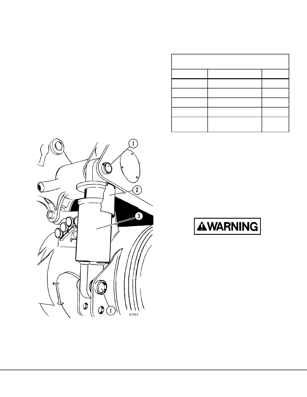
FIGURE 3-1. REAR SUSPENSION INSTALLATION
1. Mounting Pins
2. Piston Rod Shield
3. Suspension Cylinder
TABLE 1. TOOL LIST FOR SUSPENSION PIN
REMOVAL
Part Number Description Quantity
EJ2847 Pin Removal Tool 2
EJ2848 Cylinder 1
EJ2849 Hand Pump 1
EJ2850 Shackle 2
VN2707
Capscrew
(0.625-11UNC x 2.75 in)
4
 Loading...


