H2-4 Front Suspensions H02016
“TURN-OF-THE-NUT” Tightening
Procedure
a. Tighten all fourteen capscrews (1, 6, 8, Figure
2-3) to 400 ±40 ft .lbs. (542 ±5 N.m) torque.
Use a torque wrench of known calibration.
b. Maintain this torque on the top two corner cap-
screws and the bottom outer four capscrews
(item 8, the 4 bottom capscrews with nuts).
c. Loosen the 8 remaining capscrews and then
tighten again using “turn-of-the-nut” tightening
procedure as follows:
d. For the four, 6.0 in. (15 cm) long capscrews
(1,
Figure 2-3) at the upper mount, tighten cap-
screws initially to 70 ft. lbs. (95 N.m) torque;
then advance capscrew head 60° using steps
d-1.) through d-3.). Refer to Figure 2-5.
For the four inner, 12.5 in. (32 cm) long cap-
screws (6, Figure 2-3), tighten capscrews ini-
tially to 150 ft. lbs. (203 N.m) torque; then
advance capscrew head 90° using steps d-1).
through d-3). Refer to Figure 2-6.
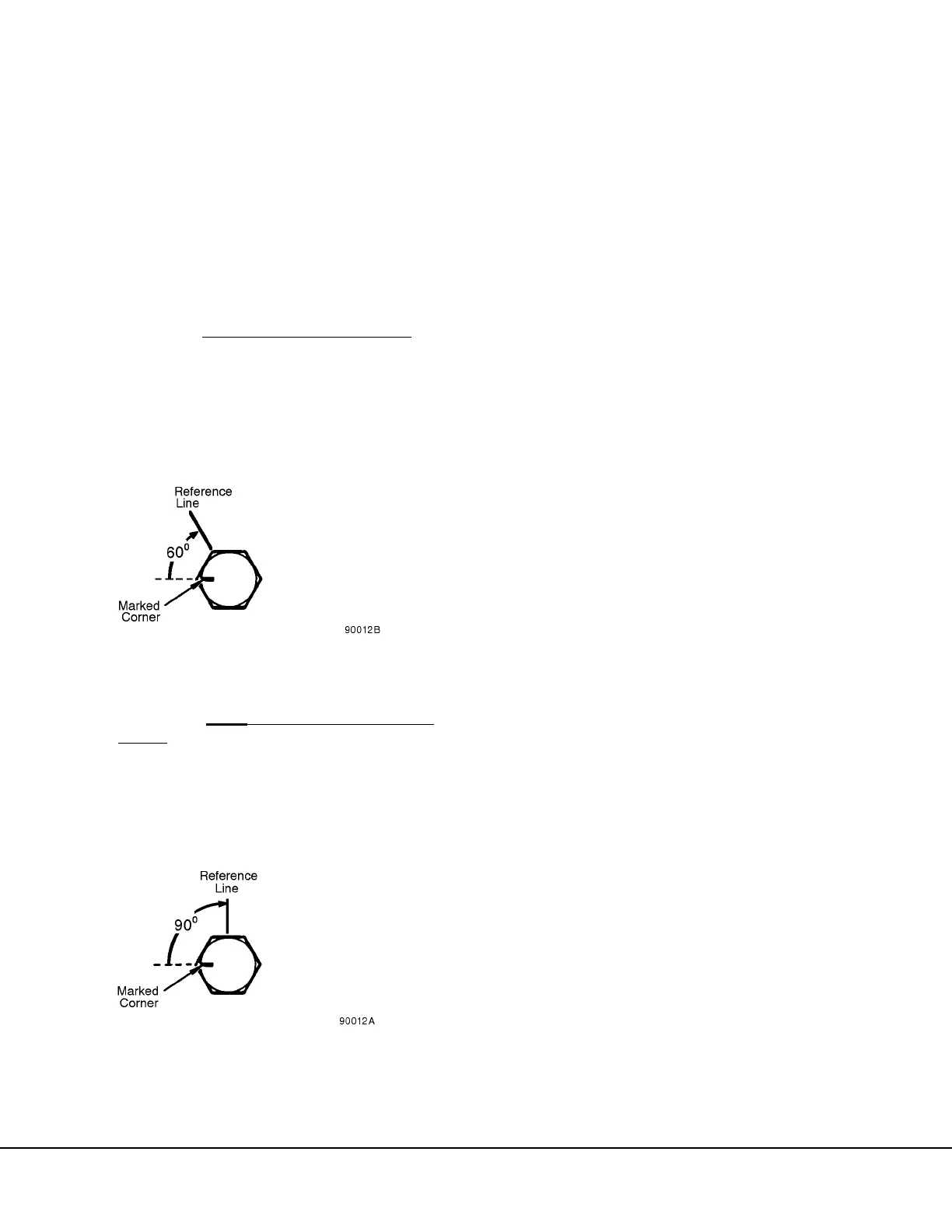
1.) Mark a reference line on a corner of the hex-
agonal capscrew head or nut and the mount-
ing surface opposite this corner as shown.
Then mark the position located 60° or 90°
clockwise relative to the first reference line
on the mounting surface. Refer to Figures 2-
5 and 2-6.
2.) To insure that the opposite end of the turning
member, either the capscrew head or nut
remains stationary, scribe a reference mark
for this check.
3.) Each corner of a hexagon represents 60°.
The turning members, either the capscrew
head or nut, is turned until the marked cor-
ner is adjacent with the marked reference
line. Check to make sure that the opposite
end of the turning member has NOT turned
during the tightening procedure. NOTE: Do
not exceed 4 RPM tightening speed. Do
not hammer or jerk wrench during the
tightening procedure.
e. Loosen the top two corner capscrews (1) and
the bottom outer four capscrews (8, the 4
bottom capscrews with nuts).
1.) Tighten the top, two corner 6.0 in. (15 cm)
capscrews to 70 ft. lbs. (95 N.m) torque,
then use “turn-of-the-nut” method to
advance capscrew heads 60°.
2.) Tighten the bottom, outer four 12.5 in. (32
cm) capscrews to 150 ft. lbs. (203 N.m)
torque, then use “turn-of-the-nut” method to
advance capscrew heads 90°.
NOTE: If for any reason, these fasteners need to be
checked for tightness after completing the above pro-
cedure; loosen and inspect all 14 capscrews and
repeat entire process, starting with cleaning and lubri-
cating capscrews, washers, and nuts. In addition, the
capscrew head will need to be appropriately marked to
show an additional use.
7. Charge suspension with dry nitrogen to fully
extend suspension piston before installing front
wheel hub and spindle.
8. Install wheel, spindle, and tire according to
instructions in Section “G”.
9. Service the suspension. For instructions refer to
HYDRAIR
®
II “Oiling and Charging Procedure”.
10. Install suspension boot and secure with clamp.
FIGURE 2-5. REFERENCE MARKS FOR 60°
ADVANCE (6.0 in. Capscrews)
FIGURE 2-6. REFERENCE MARKS FOR 90°
ADVANCE (12.5 in. Capscrews)
 Loading...


