Installation
1. Move the brake valve assembly into position and
secure in place with capscrews and lockwashers.
Tighten capscrews to standard torque.
2. Remove plugs from brake valve assembly and
hydraulic lines. Install fittings and connect lines to
brake valve assembly and tighten. Connect differ-
ential pressure switch to harness.
NOTE: Prior to checking the brake valve operation, the
steering system must have the proper nitrogen pre-
charge in the steering accumulators (refer to Section
L, “Hydraulic System” for steering accumulator pre-
charge procedure). In addition, the brake system lines
must be bled of air and the brake accumulators must
also be precharged with nitrogen (refer to brake accu-
mulator precharge procedures, this section).
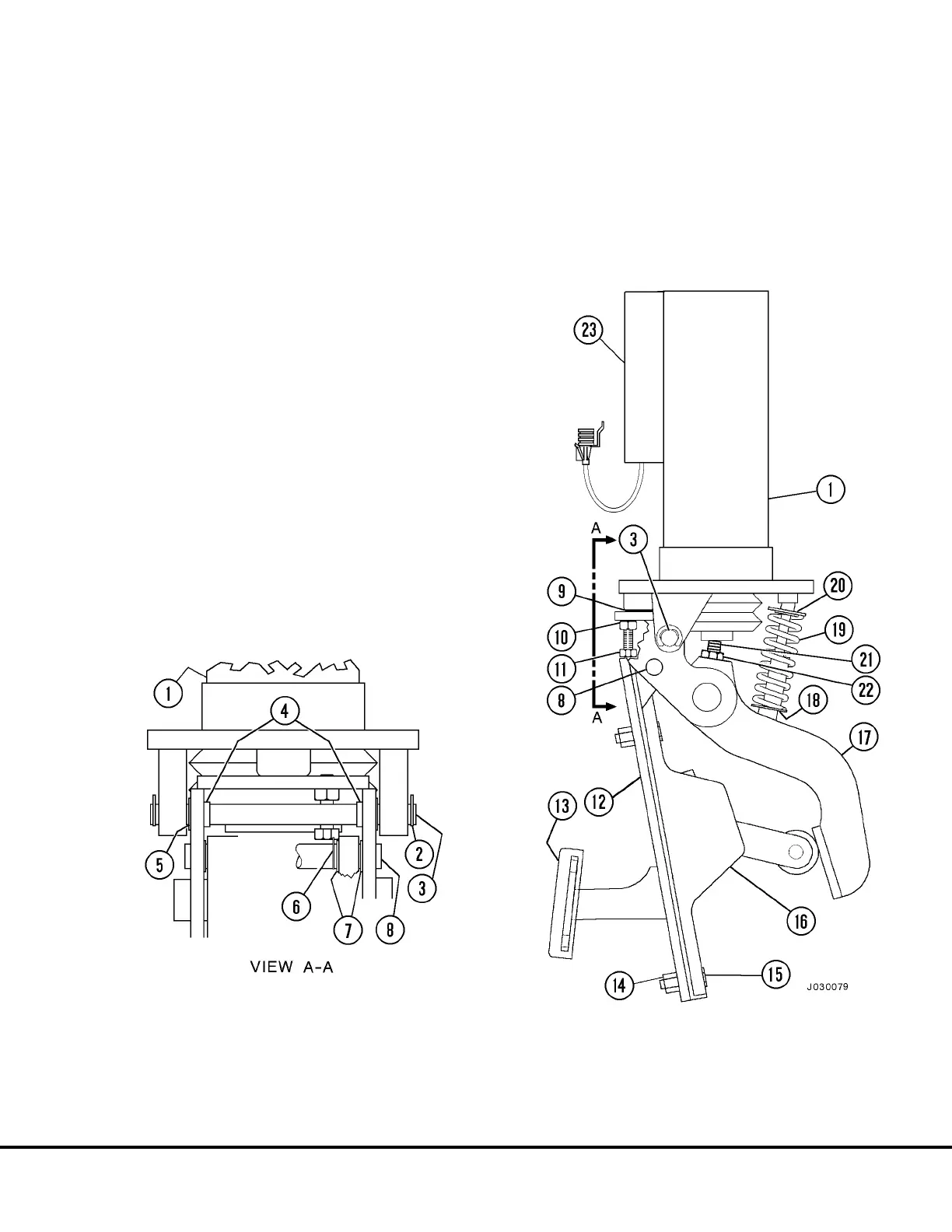
3. If equipped, install electronic retard pedal to brake
pedal (Figure 3-3).
4. With the engine shut down and key switch OFF,
open both brake accumulator bleed down valves.
Precharge both accumulators.
NOTE: For best performance, charge the accumula-
tors in the temperature conditions the vehicle is ex-
pected to operate in. During the precharge, allow
temperature of the nitrogen gas to come into equilib-
rium with the ambient temperature.
5. Close both accumulator bleed down valves after
precharge is complete.
NOTE: To prevent excess oil from coming in contact
with the brake assemblies during the brake bleeding
procedure, attach a hose to the bleeder screw. Direct
the hose into a container.
1. Brake Valve
2. Retainer Clip
3. Pivot Shaft
4. Bushings
5. Shims
6. Retainer Clip
7. Nylon Bearing
8. Pivot Shaft
9. Place 0.025 in. Shim Here
10. Jam Nut
11. Capscrew
12. Pedal Structure
13. Pad
14. Nut
15. Capscrew
16. Electronic Retard
Pedal Assembly
17. Brake Pedal Actua-
18. Spring Pivot (Lower)
19. Spring
20. Spring Pivot (Top)
21. Set Screw
22. Jam Nut
23. Differential Pressure Switch
FIGURE 3-3. BRAKE VALVE WITH RETARD PEDAL
J03022 1/99 Brake Circuit Component Service J3-3
 Loading...


