Before disabling brake circuit, be sure truck
wheels are blocked to prevent possible roll-away.
1. Securely block the wheels to prevent possible
roll-away.
2. Turn key switch OFF and allow 90 seconds for
steering system accumulators to bleed down.
Open valves (10 & 12, Figure 3-1) to bleed down
both brake accumulators.
3. Remove access panel in front of operator’s cab.
4. Tag and remove all hydraulic lines from brake
valve. Plug lines and ports to prevent possible
contamination. Remove all valve fittings. Discon-
nect wiring harness at differential pressure switch
connector.
5. If equipped, remove retard pedal that is located
on brake pedal.
6. In the cab at the brake valve, remove capscrews
and lockwashers securing the brake valve as-
sembly to the mounting structure.
7. Slide brake valve downward and remove from
cab.
8. Move brake valve assembly to a clean work area
for disassembly.
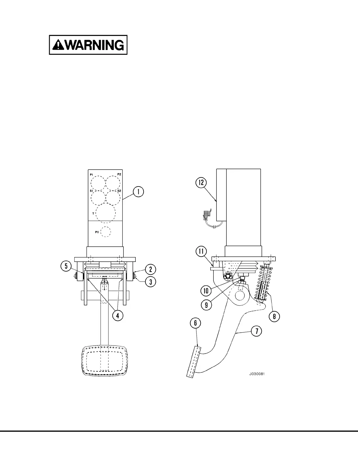
FIGURE 3-2. SINGLE PEDAL BRAKE VALVE ASSEMBLY
1. Brake Valve
2. Retainer Clip
3. Pivot Shaft
4. Bushings
5. Shims
6. Foot Pad
10. Set Screw
11. Pedal Return Stop
12. Differential Pressure Switch
7. Brake Pedal Actuator
8. Spring Assembly
9. Jam Nut
J3-2 Brake Circuit Component Service J03022 1/99
 Loading...


