E2-62 Electrical Propulsion Components 2/02 E02016
MISCELLANEOUS ELECTRICAL PROPULSION COMPONENTS
ALTERNATOR
Refer to applicable GE publication for service and
maintenance procedures.
ELECTRIC WHEEL MOTORS
Refer to applicable GE publication for service and
maintenance procedures.
RETARDING GRIDS
Refer to applicable GE publication for service and
maintenance procedures. (Cooling Blower Only).
ELECTRONIC ACCELERATOR AND
RETARD PEDALS
The accelerator and retard pedals provide a variable
voltage signal directly to the FB140 card in the FL275
panel. During some phases of truck operation, the
FL275 panel assumes control of engine RPM to reduce
engine RPM, maintaining a power level that satisfies
the operator and system requirements. The reduction
in engine RPM results in less fuel usage and longer
component life.
As the operator depresses the pedal, the internal
potentiometer's wiper is rotated by a lever. The output
voltage signal varies in proportion to the angle of
depression of the pedal. Refer to “Electrical Checkout
Procedure” for recalibration of the applicable pedal
potentiometer.
NOTE: Some trucks are equipped with individual
pedals for service brake and retarder application
(Figure 2-29). Others utilize a single pedal combining
service brake/retarder application as shown in Figure
2-30. Refer to Section J, “Brake Circuit Component
Service” for retarder pedal removal and installation
procedure for a single pedal system. Pedal
potentiometer replacement instructions on the
following page are applicable to either type.
The retard pedal is suspended from the front wall of the
cab and the accelerator is floor mounted. Potentiome-
ter replacement procedures are the same for both ped-
als. (Refer to Figures 2-28 and 2-29.)
Removal
1. Disconnect pedal wire harness from truck har-
ness at the connector.
2. Remove mounting capscrews, lockwashers and
nuts and remove pedal assembly.
NOTE: Note proper routing and clamp location of wire
harness. Proper wire routing is critical to prevent
damage during operation after reinstallation.
Installation
1. Install pedal assembly using hardware removed
in step 2, “Removal”. Connect potentiometer har-
ness to truck wiring harness.
2. Calibrate throttle potentiometer per instructions in
“Throttle System Check and Adjustment”, Section
E3.
3. Calibrate retard pedal potentiometer per instruc-
tions in “Retard System Check and Adjustment -
Electronic Pedal System”, Section E3.
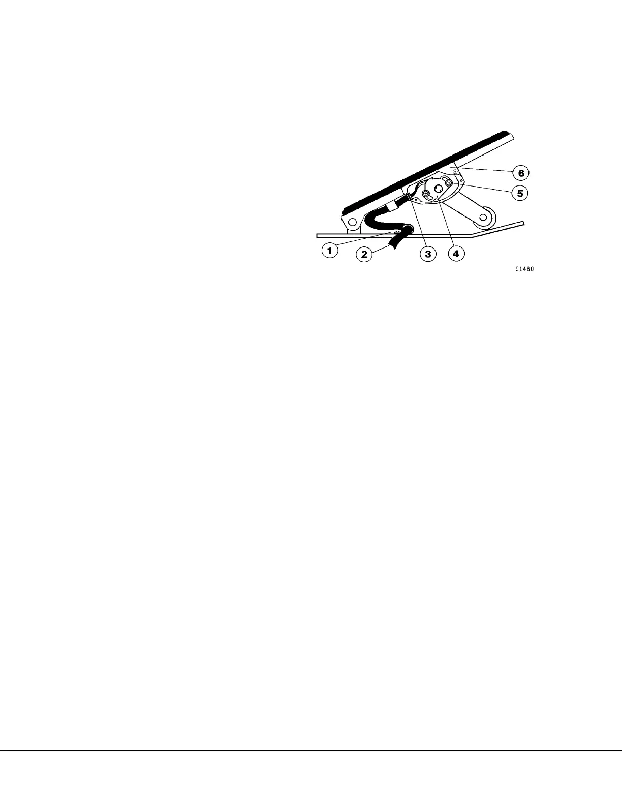
FIGURE 2-28. ELECTRONIC ACCLERATOR PEDAL
1. Clamp and Screws
2. Harness
3. Grommet
4. Potentiometer
5. Mounting Screws
6. Cover
 Loading...


