E02016 2/02 Electrical Propulsion Components E2-63
Disassembly
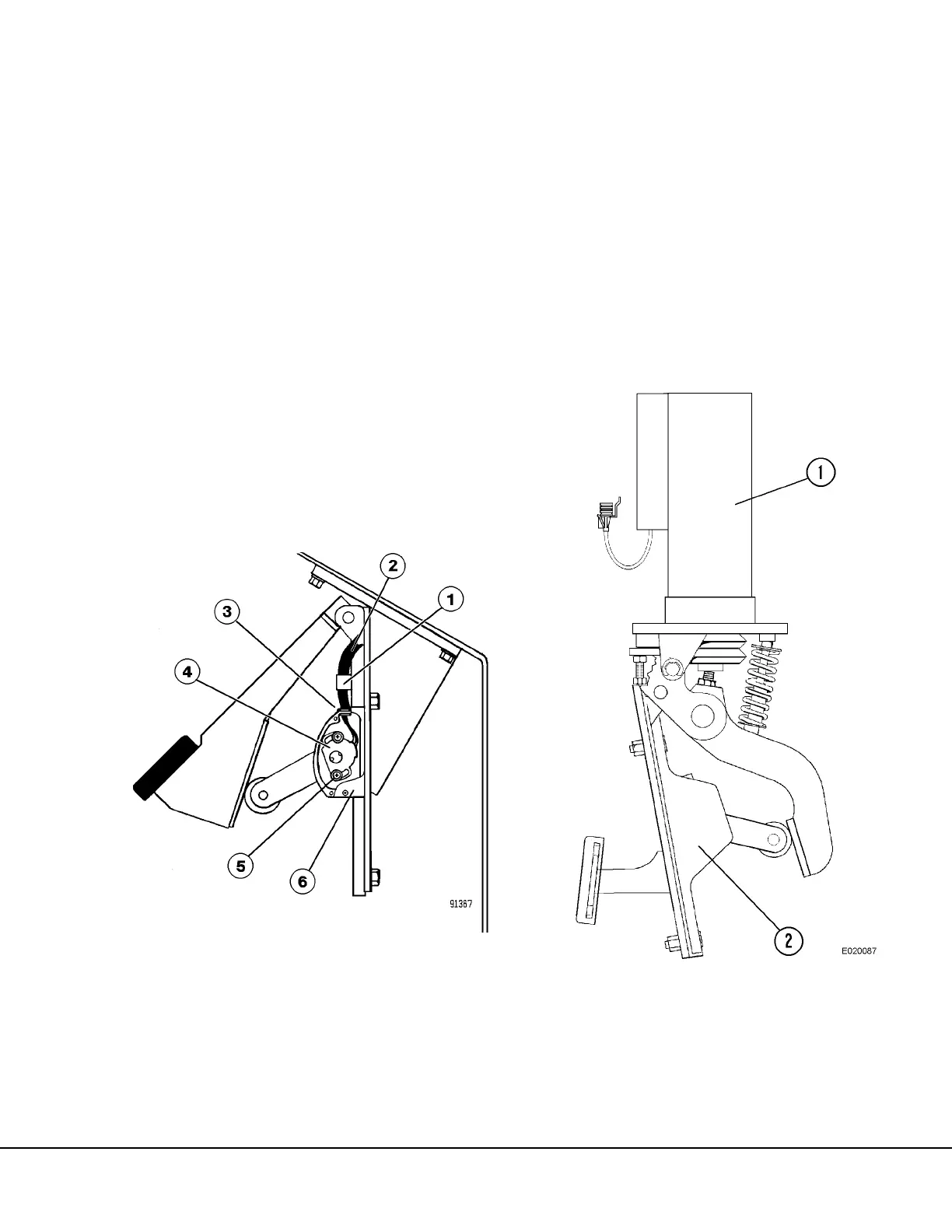
1. Remove screws on cable clamps (1, Figure 2-28
or 2-29) and potentiometer cover (6).
2. Remove potentiometer mounting screws (5) and
grommet (3). Remove potentiometer (4).
Reassembly
1. Position new potentiometer with the flat side
toward the potentiometer cover and install on
shaft as follows:
a. Align cutouts in shaft with the potentiometer
drive tangs.
b. Press potentiometer onto shaft until it bottoms
against the housing.
2. Install screws (5, Figure 2-28 or 2-29) and lock-
washers but do not tighten.
3. Rotate potentiometer counterclockwise until
mounting slots contact the mounting screws and
tighten screws (5) to 10-20 in lbs. (1.13-2.26 N-
m) torque.
4. Install grommet (3) and potentiometer cover.
Tighten screws to 10-20 in lbs. (1.13-2.26 N-m)
torque.
5. Install cable clamps and tighten screws to 35-45
in. lbs. (3.4-5.1 N-m) torque.
6. Inspect assembly and verify proper wiring clear-
ance during operation of pedal throughout the
range of travel.
FIGURE 2-29. ELECTRONIC RETARD PEDAL
(Two Pedal System)
1. Clamp and Screws
2. Harness
3. Grommet
4. Potentiometer
5. Mounting Screws
6. Cover
FIGURE 2-30. BRAKE/RETARDER PEDAL
(Single Pedal System)
1. Service Brake Valve 2. Electronic Retard
Pedal

 Loading...


