N03018 Cab Components N3-1
CAB COMPONENTS
WINDSHIELD WIPERS
The windshield wipers are operated by a 24 volt elec-
tric motor. The wipers can be adjusted for a variable
intermittent delay or a constant low or high speed by
the switch mounted on the instrument panel.
Wiper Motor
Removal
1. Remove the five screws inside of the cab that
secure the visor assembly/access panel. Lower
the access panel.
2. Disconnect the wiper motor harness connector.
3. While holding the linkage stationary, remove nut
(4, Figure 3-1) and disconnect the linkage from
the motor.
4. Remove three capscrews (3) with washers
attaching the wiper motor to plate (2). Remove
the motor assembly.
Installation
1. Place wiper motor (1, Figure 3-1) into position
on plate (2).
2. Install three capscrews (3) with washers.
Tighten capscrews to 71-79 in. lbs. (8-9 Nm)
torque.
3. Align the motor output shaft with the wiper link-
age. Install nut (4) and while holding the linkage
stationary, tighten nut to 16-18 ft. lbs. (22-24
Nm) torque.
4. Reconnect the wiper motor harness connector.
5. Verify the wipers operate properly and park in
the proper position. Refer to Figure 3-3.
Wiper Arm
Removal
1. Note the parked position of wiper arm (1, Figure
3-2).
2. Lift the wiper arm cover and remove nut (2) and
washer (3).
3. Disconnect the washer hose, and remove the
wiper arm.
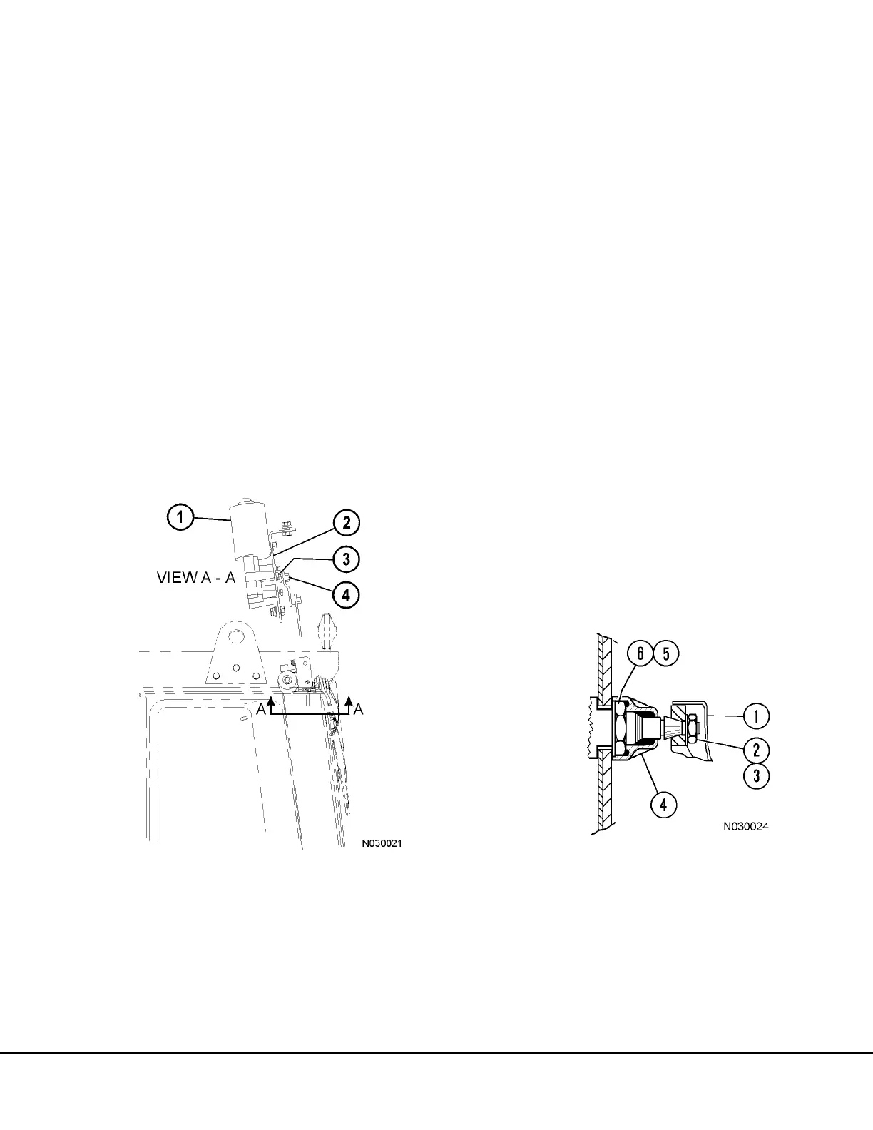
FIGURE 3-1. WINDSHIELD WIPER INSTALLATION
1. Wiper Motor
2. Plate
3. Capscrew
4. Nut
FIGURE 3-2. WIPER ARM DETAIL
1. Wiper Arm
2. Nut
3. Spring Washer
4. Cap
5. Washer
6. Nut
 Loading...


