N3-2 Cab Components N03018
Installation
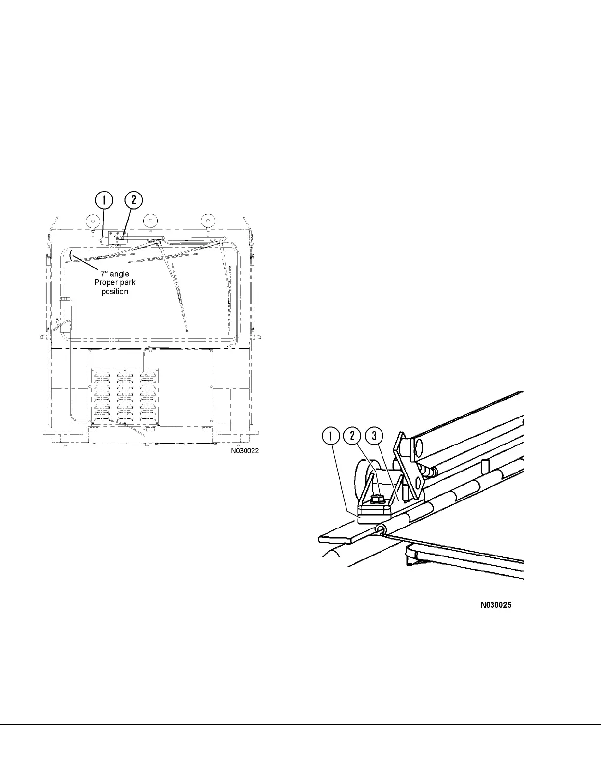
1. Place wiper arm (1, Figure 3-2) into the position
noted during removal. Install washer (3) and
nut (2). Tighten the nut to 142-177 in. lbs. (16-
20 Nm) torque. Close the cover.
2. Connect the washer hose to the wiper arm.
3. Ensure the wipers arms operate properly and
park in the proper position after installation is
complete. Refer to Figure 3-3.
Wiper Linkage
Removal
1. Remove the wiper arms. Refer to Wiper Arm
Removal in this section.
2. Remove wiper retainer (2, Figure 3-3) and dis-
connect the wiper linkage from the wiper motor
drive arm.
3. Remove nut (6, Figure 3-2) and the washer (5)
from each wiper shaft.
4. If equipped, remove four capscrews (2, Figure
3-4) with washers.
5. Remove the pillow blocks (3) from the wiper
compartment.
Installation
1. Place the linkage into position in the wiper com-
partment.
2. Install pillow blocks (3, Figure 3-4). Install cap-
screws (2) with washers and tighten capscrews.
3. Install nut (6, Figure 3-2) with washer (5) on
each wiper shaft and tighten finger-tight.
Tighten the nuts to 160-177 in. lbs. (18-20 Nm)
torque. Do not overtighten. The threads on
the shafts are easily stripped when improp-
erly tightened. Install cap (4) over nut (6).
4. Align the linkage and attach to the wiper motor
drive arm using retainer (2, Figure 3-3).
NOTE: When the motor is parked, the drive arm will
be in the 3 o’clock position as shown in Figure 3-3.
5. Install the wiper arms. Refer to Wiper Arm Instal-
lation. Ensure the wipers arms operate properly
and park in the proper position after installation
is complete.
FIGURE 3-3. PARK POSITION
1. Wiper Motor 2. Linkage Retainer
FIGURE 3-4. PILLOW BLOCK INSTALLATION
1. Spacer Block
2. Capscrew
3. Pillow Block

 Loading...


