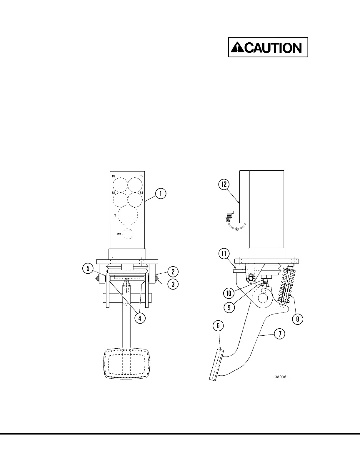
Installation Of Brake Pedal Actuator Assembly
to Brake Valve
1. Install jam nut (9, Figure 3-11) and set screw (10)
to brake pedal actuator (7).
2. Insert nylon bushings (4) into brake pedal actua-
tor.
3. Install one retaining clip (2) to one end of pivot
shaft.
4. Align pedal structure to brake valve (1) and par-
tially insert pivot pin. Move pedal structure to the
“B2” side of valve and insert shims (5) between
pedal structure and brake valve ear to fill gap.
Fully insert the pivot shaft (3). Install the remain-
ing retainer clip (2).
5. Assemble spring assembly (8) and install com-
plete assembly to brake pedal actuator as shown.
Be sure to install spring assembly correctly, with
larger ball socket end pointing to the pedal struc-
ture and smaller end toward the valve assembly.
NOTE: If pedal is adjusted properly, the spring assem-
bly will not interfere with pedal travel.
The spring and spring pivots are different for ped-
als equipped with and without the electric retard
pedal mounted to the brake pedal. DO NOT inter-
change the springs or spring pivots.
FIGURE 3-11. SINGLE PEDAL BRAKE VALVE ASSEMBLY
1. Brake Valve
2. Retainer Clip
3. Pivot Shaft
4. Bushings
5. Shims
6. Foot Pad
7. Brake Pedal Actuator
8. Spring Assembly
9. Jam Nut
10. Set Screw
11. Pedal Return Stop
12. Differential Pressure Switch
J03022 1/99 Brake Circuit Component Service J3-13

 Loading...


