G03018 04/03 Front Wheel Hub and Spindle G3-7
b. Install cups in wheel hub bores.
c. After cups have warmed to ambient temper-
ature, press the cups tight against hub shoul-
der as follows:
1.) Inner Cup (20) - Apply 30,000 lbs.
(133,450 N) force.
2.) Outer Cup (10) - Apply 23,000 lbs.
(102,300 N) force.
9. Install the other half of the seal assembly (16) in
the hub using installation tool (TY2150) and soft
tipped mallet. Follow procedure outlined in step
6.
10. Check bearing cone (9) for free fit on the spindle
(17), then remove.
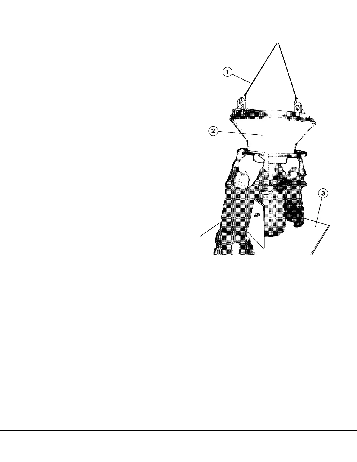
11. Referring to Figure 3-8, lift the hub and carefully
lower it down over the spindle. To aid installa-
tion and to prevent damaging the seal, the spin-
dle and hub should be level.
NOTE: All parts must be in place before wheel hub
(1) is installed.
12. Install outboard pin (25, Figure 3-5) into slot on
spindle (17) and install inner bearing cone (9)
on spindle over pin (25).
13. Refer to Wheel Bearing Adjustment for final
assembly.
FIGURE 3-8. WHEEL HUB INSTALLATION
1. Support Chains
2. Wheel Hub
3. Fabricated Support
Stand

 Loading...


