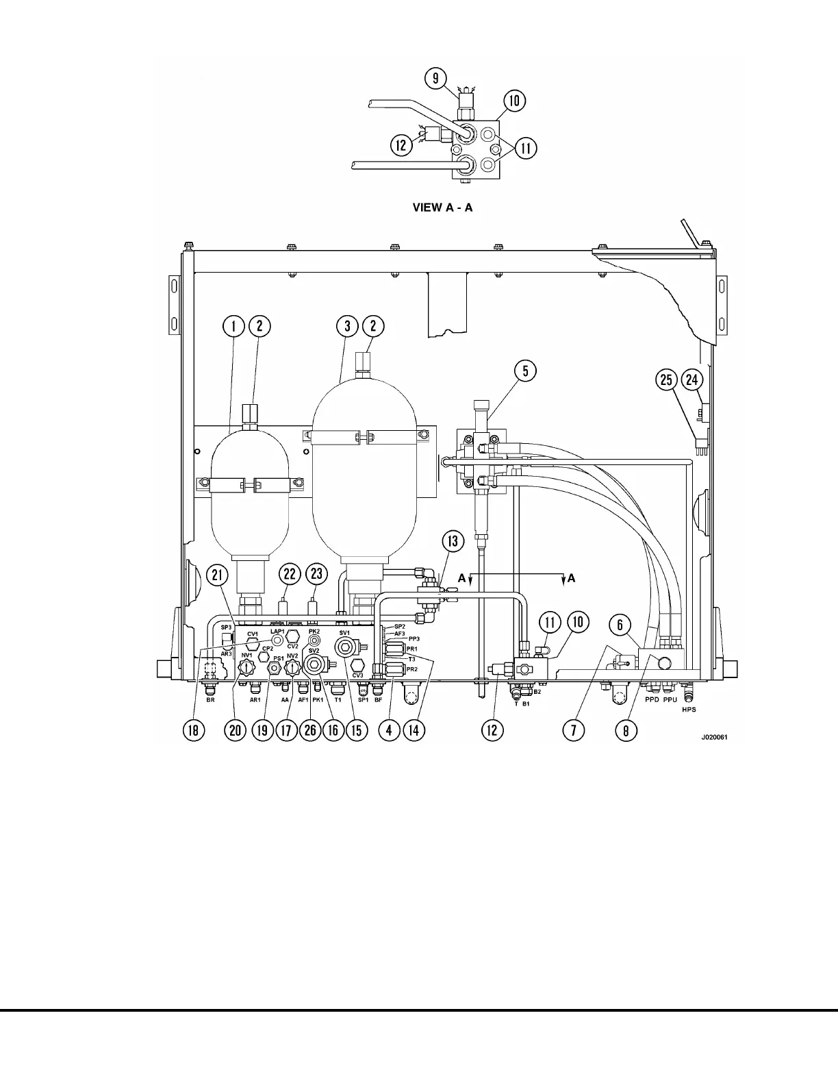
FIGURE 2-1. HYDRAULIC BRAKE CABINET
1. Rear Brake Accumulator
2. Charging Valve
3. Front Brake Accumulator
4. Park Brake Pressure Reducer Valve
5. Hoist Pilot Valve
6. Hoist Pilot Manifold
7. Hoist-Up Limit Solenoid
8. Pilot Operated Check Valve
9. Brake Lock Degradation
Pressure Switch
10. Junction Block
11. BF & BR Test Port
(Front & Rear Brake)
12. Stop Light Switch
13. Brake Lock Shuttle Valve
14. Brake Lock Pressure Reducing Valve
15. Brake Lock Solenoid
16. Park Brake Solenoid
17. Bleed Down Valve
(Front Brake Accumulator)
18. Accumulator Test Port
19. Automatic Apply Valve
20. Bleed Down Valve
(Rear Brake Accumulator)
21. Brake Manifold
22. Low Brake Accumulator
Pressure Switch
23. Park Brake Pressure Switch
24. Brake Warning Delay Timer
25. Brake Warning Light Relay
26. Park Brake Test Port
J2-2 Brake Circuit J02032

 Loading...


