3-POINT HITCH
1. Preparations for attaching the 3-
point hitch implement
1.1 Selecting the holes of lower links
1. Selecting the
proper holes of lower links to attach
the lifting rod.
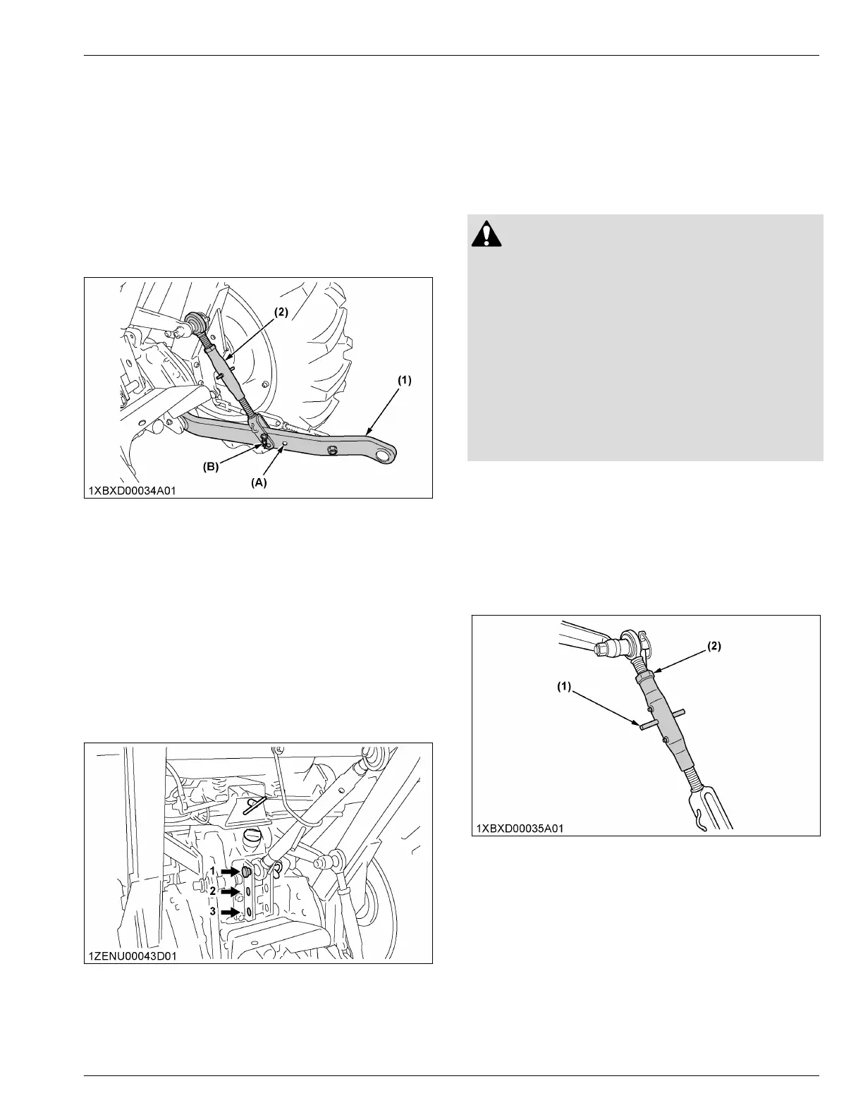
There are two holes in the lower links. For most
operations, you should attach the lifting rods to the
hole-B as follows.
(1) Lower link
(2) Lifting rod
(A)
Hole-A
(B) Hole-B
NOTE :
• You
may attach the lifting rods to the hole-A
for greater lifting force.
1.2 Selecting the holes to mount the top
link
1. Select the
proper set of holes according to
Hydraulic control unit use reference chart on page
81.
1.3 Dealing with the drawbar
1. Remove the
drawbar if a close mounted implement
is attached to the 3-point hitch.
(For detail for the drawbar, see DRAWBAR
on page
78)
2. Attaching methods of 3-point
hitch implement
2.1 Precautions for attaching and
detaching the 3-point hitch implement
WARNING
To avoid personal injury or death:
•
Be sure to stop the engine before attaching the
3-point hitch implement.
• Do not stand between tractor and implement
unless the parking brake is applied.
• Before attaching or detaching the 3-point hitch
implement, locate the tractor and implement on
a firm level surface.
• Whenever an implement or other attachment is
connected to the 3-point hitch of the tractor,
check full range of operation for interference,
binding, or PTO separation.
2.2 Adjusting the lifting rod (right)
1. Level a 3-point mounted implement from side to
side
by turning the adjusting handle with 3-point
mounted implement on the ground.
2. Shorten or lengthen the adjustable lifting rod.
3. After adjustment, tighten the lock nut securely.
(1) Adjusting handle (2) Lock nut
2.3 Adjusting the top link
The proper length of the top link varies according to the
type of implement being used.
1. Adjust the angle of the implement to the desired
position by shortening or lengthening the top link.
2.
After adjustment, tighten the lock nut securely.
3-POINT HITCH 3-POINT HITCH AND DRAWBAR
 Loading...