2M4/2M5/2M6/2M7
1-5-21
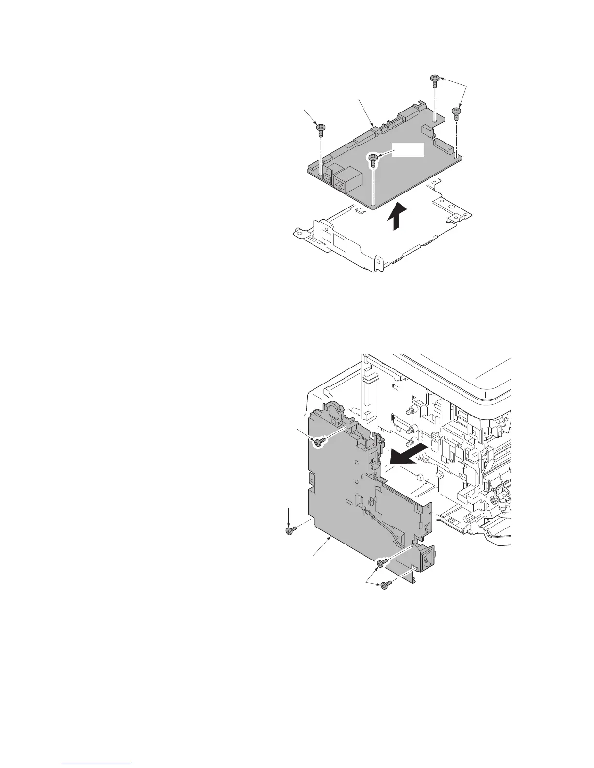
8. Remove four screws and then remove
the main PWB.
9. Check or replace the main PWB, and
refit all the removed parts.
Figure 1-5-31
(2) Detaching and refitting the high voltage PWB, power source PWB and
FAX PWB (4 in 1 model only)
Procedure
1. Remove the main PWB unit (see page
1-5-18).
2. Remove the right cover (see page 1-5-
5).
3. Remove four screws and then remove
the control unit.
Figure 1-5-32
Main PWB
Screw
Screws
Screw
Screw
Screw
Screws
Controller
unit
 Loading...