2M4/2M5/2M6/2M7
2-2-1
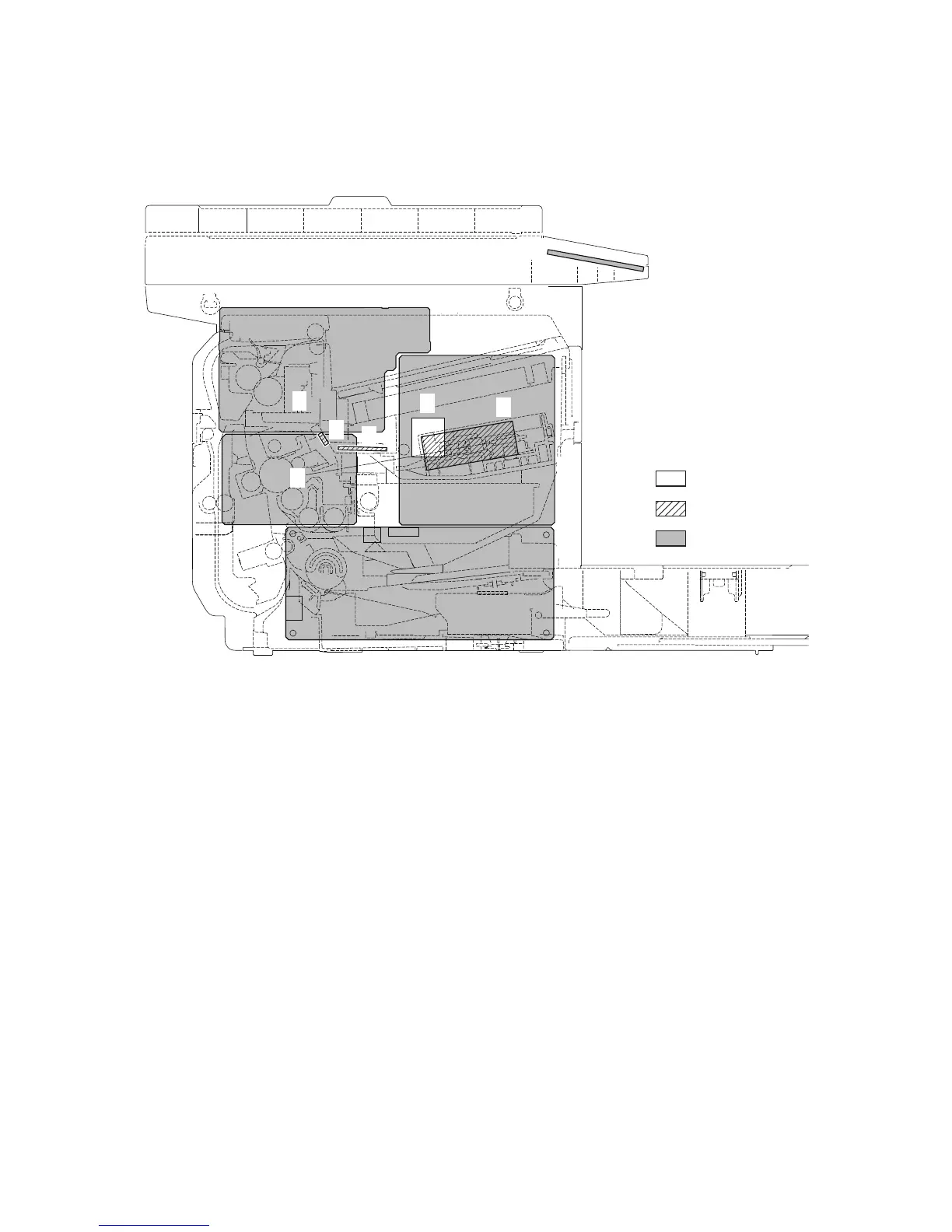
2-2 Electrical Parts Layout
2-2-1 Electrical parts layout
(1) PWBs
Figure 2-2-1 PWBs
1. Main PWB (MPWB) .............................. Main controller: Controls the software such as the print data
processing and provides the interface with computers.
Engine: Controls machine hardware such as high voltage/bias
output control, paper conveying system control, and fuser temper-
ature control, etc.
2. Relay PWB (RPWB) ............................. Consists of wiring relay circuit between main PWB and Main
motor, toner sensor, container sensor, registration sensor, paper
feed solenoid, duplex solenoid.
3. Power source PWB (PSPWB) .............. After full-wave rectification of AC power source input, switching
for converting to 24 V DC for output.Controls the fuser Heater.
4. High voltage PWB (HVPWB) ................ Generates main charging, developer bias and transfer bias.
5. Container PWB (CPWB) ....................... Reads the container information.
6. Operation panel PWB(OPWB).............. Consists the LED indicators and key switches.
7. APC PWB (APCPWB) .......................... Generates and controls the laser beam.
8. Eraser lamp PWB (ELPWB) ................. Eliminates the residual electrostatic charge on the drum.
9. FAX control PWB (FCPWB)* ................ Modulates, demodulates, compresses, decompresses and
smoothes out image data, and converts resolution of image data.
*: 4 in 1 model only.
1
2
3
4
5
6
7
8
Machine inside
Machine left
Machine right
9
 Loading...