Configuration
7-46
48XX/49XXSHB0399
7.3.3 Slave for digital frequency cascade
Purpose
With configuration C005 = -72- for the set-value cascade
( the phase control which is connected to the speed controller will be
activated
( the set-value path is changed to digital frequency coupling for speed ratio
synchronism.
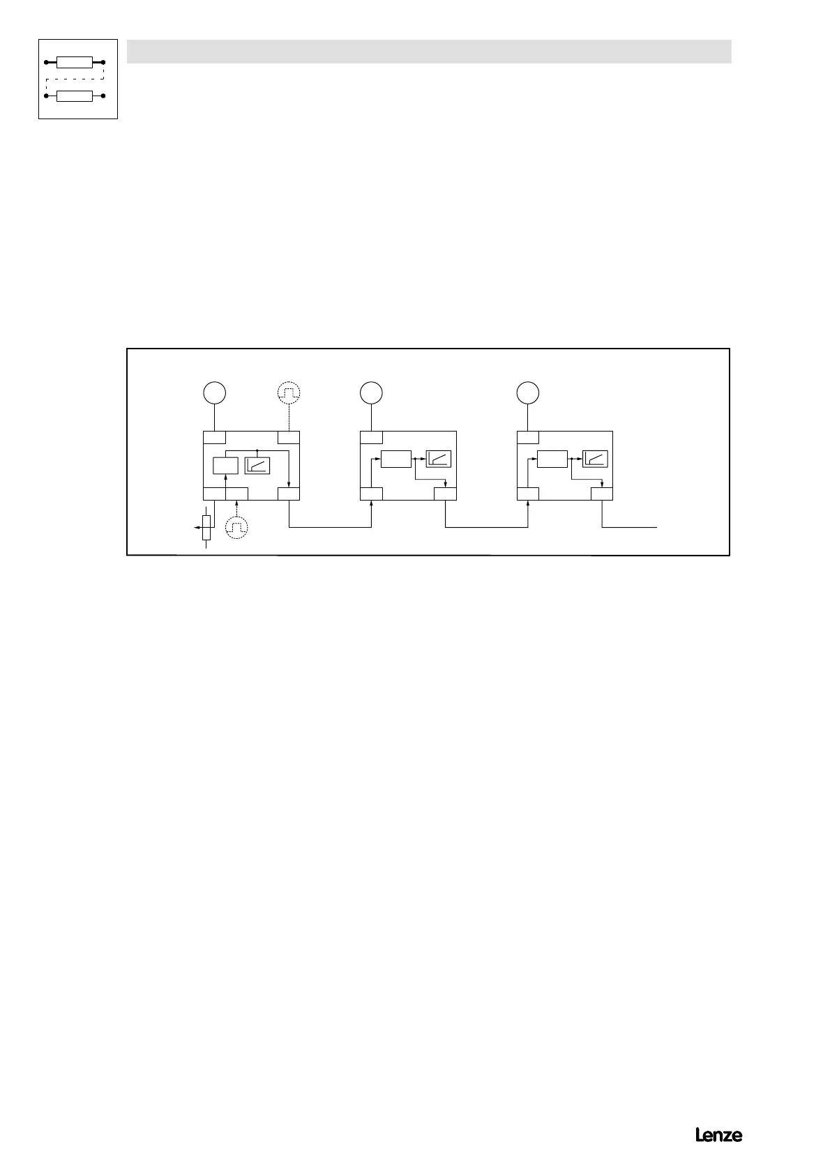
4900Str044
X7 X5
X8X1 X9
SW I
R
X7
X8X5
R
X7
X8X5
Factor
R
j , n -c trl.
Encoder
output
Resolver
Increm ental
encoder
M aster drive w ith
m aster integrator
Factor
j
, n -c trl
Encoder
output
Resolver
Slave 1
j
, n -c trl.
Encoder
output
Resolver
Slave 2
FIG 7-17 Connection diagram for the configuration of the digital frequency cascade
Features
( Only resolver feedback possible
( With a cascading factor evaluation of the set-value
(numerator/denominator) possible for the digital frequency output and thus
for all following drives adjustable via LECOM, motor potentiometer or
analog terminal
( Another evaluation of the set-value with a factor (numerator/denominator)
for the corresponding slave (gearbox adaptation). Adjustable via LECOM,
motor potentiometer or analog terminal
( External torque limitation possible
( The QSP or RFR function in the individual drive do not influence the
set-value of the cascade
( Influence possible via codes for phase trimming and speed correction (via
LECOM, motor potentiometer, analog termina or signal source (C145))
( Following error limit adjustabel via code
( TRIP when reaching the phase controller limit
( Speed limit = 1.8 ¼ C011
( Phase controller influence of 0 (0 = deactivated) adjustable up to 1.00
( No alternative set-value conditioning available (JOG, additional set-value,
set-value integrator, ...)

 Loading...