EasyManua.ls Logo

Lenze 4800 User Manual

Lenze 4800
342 pages
To Next Page IconTo Next Page
To Previous Page IconTo Previous Page
Page #174 background imageLoading...
Page #174 background image
Configuration
7-83
48XX/49XXSHB0399
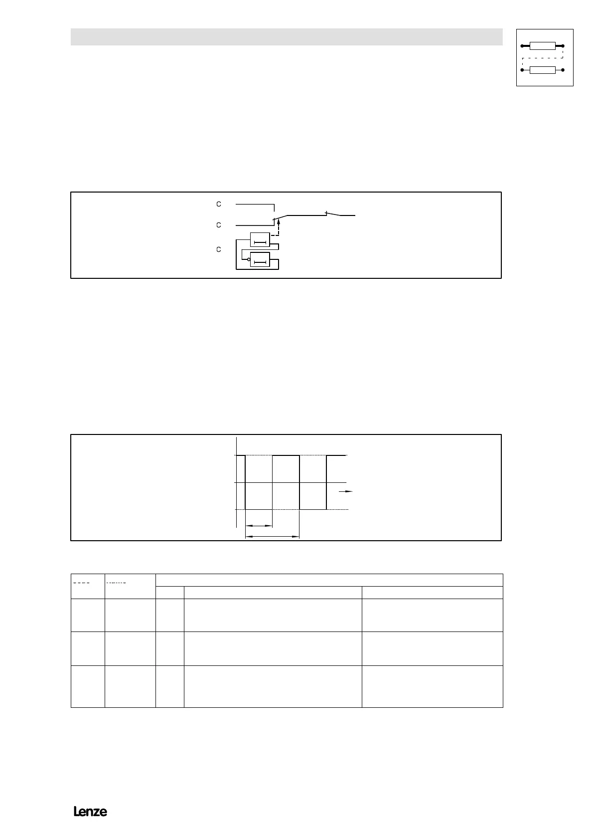
7.5.9 Square-wave generator
Purpose
The square-wave generator accepts jump responses from the control circuits.
Parameter setting
4900Str068
C 145/C 146
1
0
0t
0t
C
670
C
671
C
672
FIG 7-41 Square-wave generator
1. Input
The amplitude is set under C670 (upper value) and C671 (lower value).
2. Outputs
With the function freely assignable analog inputs the output can be assigned to
the targets listed under C146.
3. Function
The transfer time is set under code C672. The period results from T = 2 ¼ C672.
4900Str069
T
C 672
C 671
C 670
t
FIG 7-42 Signal flow at the square-wave generator
Code
Name
Possible settings
C
o
d
e
N
a
m
e
Lenze Selection Info
C670* Square-wave
generator
upper limit
0% -100.0 % {0.1 %} +100.0 % C670 must be higher than C671!
C671* Square-wave
generator
lower limit
0% -100.0 % {0.1 %} +100.0 % C671 must be smaller than C670!
C672* Switch-over
time of the
square-wave
generator
0.1 s 0.1 s {0.1 s} 10 s
10 s {1 s} 100 s
100 s {10 s} 3000 s
Show/Hide Bookmarks

Table of Contents

Question and Answer IconNeed help?

Do you have a question about the Lenze 4800 and is the answer not in the manual?

Lenze 4800 Specifications

General IconGeneral
BrandLenze
Model4800
CategoryController
LanguageEnglish

Summary

Safety information

General safety information

Provides essential safety notes for operation, potential hazards, and general precautions.

Technical Data

Features

Outlines the key controller and system features, including operational capabilities and interface options.

Rated data

Details electrical ratings, including output power, voltages, currents, and thermal data for different controller types.

Installation

Electrical installation

Details electrical safety, connection procedures, and isolation requirements.

Commissioning

Initial switch-on

Guides through the initial power-up procedure, wiring checks, and essential switch-on sequence.

Input of the motor data

Explains the importance and method for inputting motor nameplate data for accurate controller calculations.

Controller enable

Details the conditions and methods for enabling the controller via terminal or LECOM interface.

During operation

Configuration

Speed controlled operation

Covers configuring the drive for speed control, including detailed set-value selection methods.

Torque control with speed limitation

Explains how to set up the drive for torque control while maintaining speed limitations.

Troubleshooting and fault elimination

Troubleshooting

Guides users through identifying and resolving operational issues using controller displays and status information.

Fault analysis with the history buffer

Explains how to use the history buffer to trace and analyze faults for effective troubleshooting.

Signal-flow charts

Related product manuals