Installation
4-6
48XX/49XXSHB0399
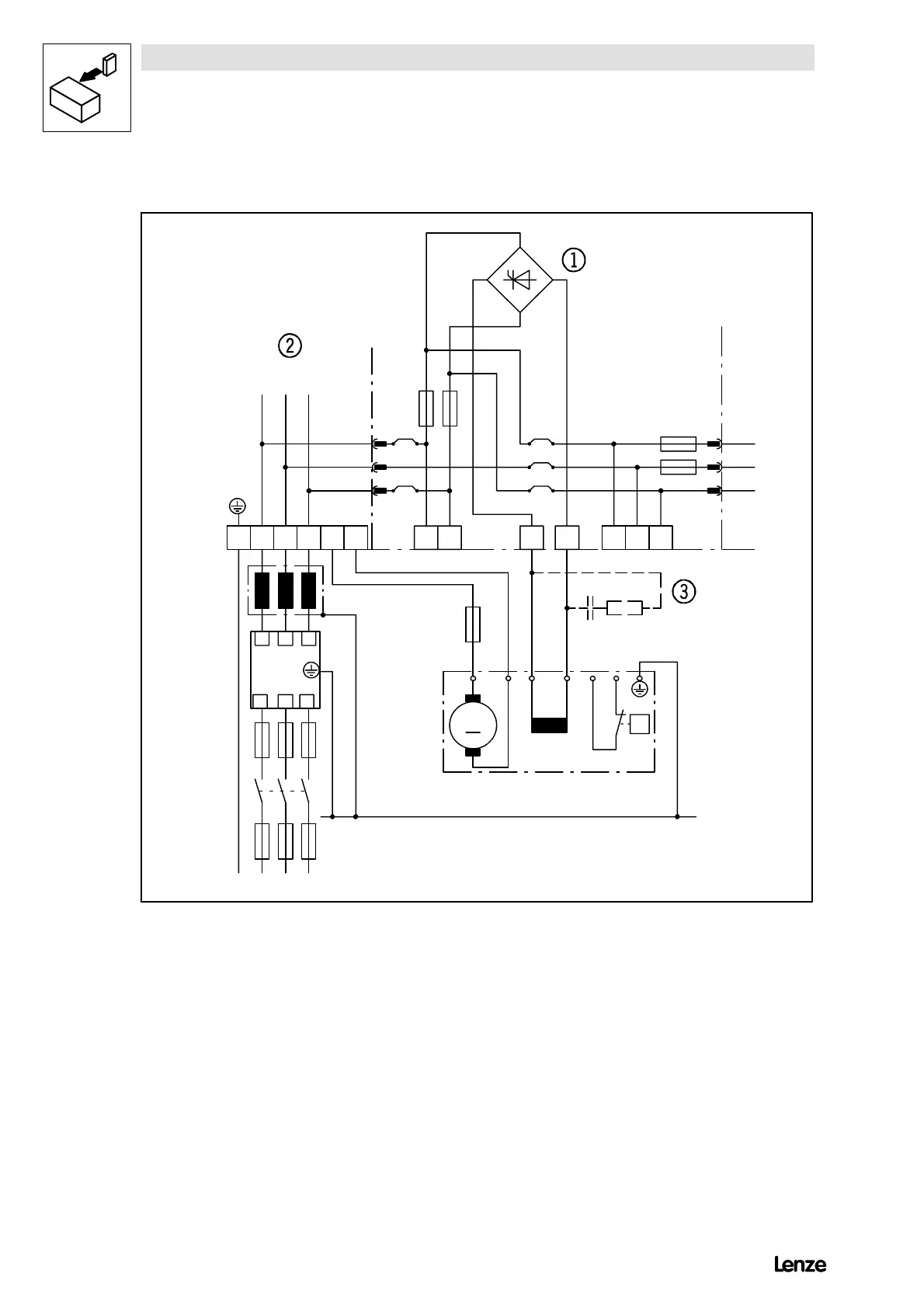
4.3.1 Power connection of standard controller
Z1
K1
F’1...F’3
L
K
F’’1...F’’3
L1 L2 L3
L1 L2 L3
L’1L’2L’3
L1 L2 L3PE B
F’4
M
M1
A
IKAB S1 S2
IKL1.2L2.2 L3.2
PE
L3.1L1.1
FF16A
500V
4902/3/5LP 4902VP
F4
F3
M0,5A 500V
F1 F2
BR1
BR2
BR5
BR3
BR4
RC
PE
V
mains
= 340 ... 460 V~ 0% 50 ... 60 Hz
J
4900Str003
FIG 4-3 Power connection of controllers 4902 to 4907
K1 Mains contactor
F’1...F’4 Semiconductor fuses for controller protection
F’’1...F’’3 Line protection fuses
L
K
Commutating choke (mains choke)
Z1 RFI filter
BR1 - BR5 0W wire bridge
¥
Field controller
¦
Power stage
§
Auxiliary starting circuit
With field voltages > 300V and field currents < 200mA an auxiliary starting circuit should be used.
Recommended dimensioning: R = 330 W/20W; C=0.22mF/400V AC.

 Loading...