Selection aid
15-25
48XX/49XXSHB0399
Contactor or relay circuit
4900Str110
20 21 28 39 40 59 90 FE
X2 X3 X4
4900
22 A4
K3
S1
S2
K2
K2 K2.1
K1
K2.1
K4
K3
K1
td
L11
L10
L20
K4 K5
K4
S4
K2
S3
12
K5
K1
RFR
R
L
QSP
n a c t = 0
td > tB r.
D irect connection to control cable "O N "
"Em ergency off" cable
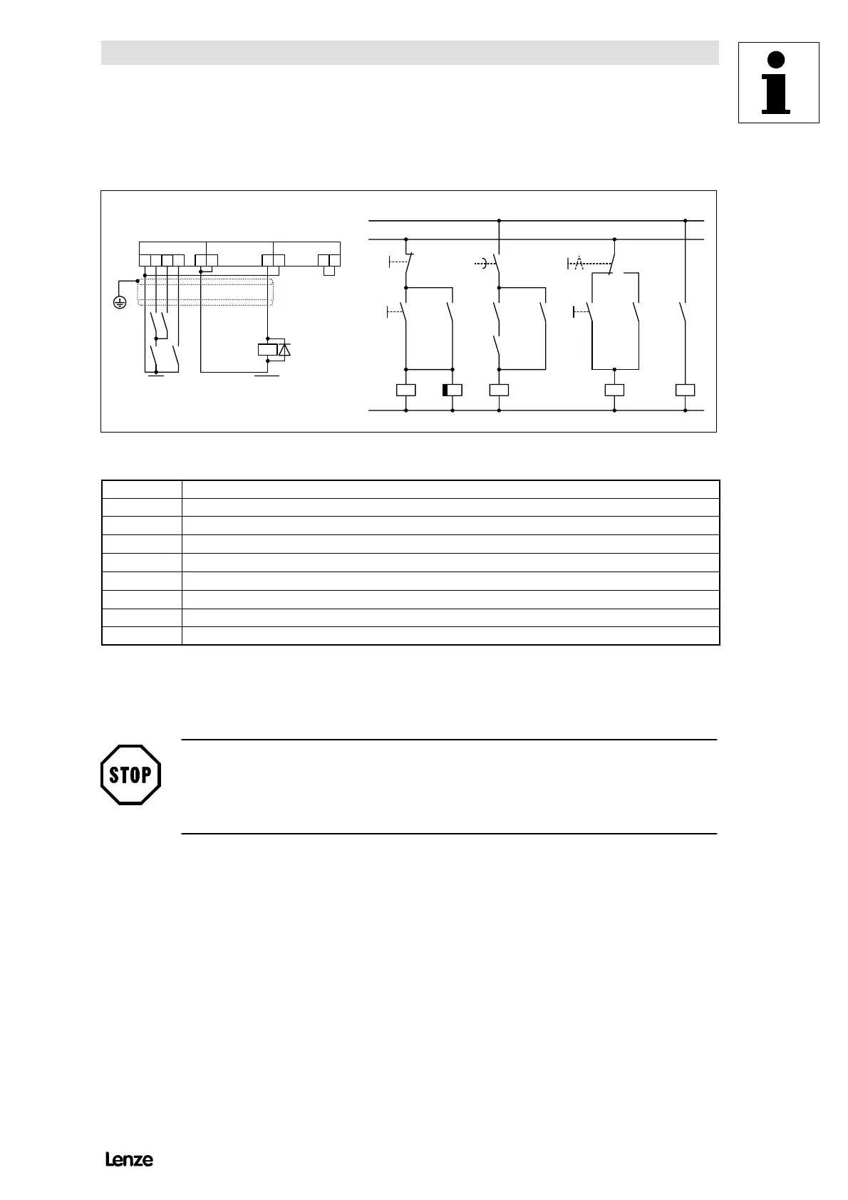
FIG 15-12 Connection of the signal electronics for tipping operation via momentary-contact pushbutton S4
K1
Controller mains contactor
K2.1 Safety relay for mains isolation if no standstill message is indicated
K4, K5 Relay with gold-plated contacts
S1 Drive off
S2 Drive on
S3 1: Tipping / 2: Automatic
S4 Inching
L10 Direct cable from the control cable ’on’
L11 ’Emergency-Off cable
15.9.2 Mains switch-off logic
Stop!
The controllers 48XX/49XX must only be separated from the mains when they are
inhibited or the motor is in standstill.
This also applies to the emergency-off function.
The function |n
act
| < C019 can be used for the mains switch-off logic.
The digital output terminal A4 is for automatic mains switch-off. The terminals sets
”low”, if the actual speed value is lower than the value set under C019. The
threshold can be set under C019 from 0 to 5000 rpm. For this application, the
setting must not exceed 2% n
rated
.

 Loading...