EasyManua.ls Logo

Lenze 4800 User Manual

Lenze 4800
342 pages
To Next Page IconTo Next Page
To Previous Page IconTo Previous Page
Page #172 background imageLoading...
Page #172 background image
Configuration
7-81
48XX/49XXSHB0399
7.5.8 Addition
Purpose
The controller provides two addition facilities with three inputs each. Here, analog
signals can be added or subtracted.
Parameter setting
4900Str066
C 146/C 147
C 145/C 146
C 610
C 145/C 146
±200 %
+ +
+-
C 146/C 147
C 611
C 146/C 147
C 612
In p u t 1
Output 1
Output 2
In p u t 2
In
p
u t 3
FIG 7-39 Addition 1
4900Str067
C 146/C 147
C 145/C 146
C 614
C 145/C 146
±200 %
+ +
+-
C 146/C 147
C 615
C 146/C 147
C 616
In p u t 1
Output 1
Output 2
In p u t 2
In
p
u t 3
FIG 7-40 Addition 2
1. Input
With the function freely assignable analog inputs each input can be assigned to
a terminal signal from the table in C145. If signals are assigned to the inputs, the
input codes are for display only. If the inputs are not assigned, constant values can
be assigned via the input codes. These values can also be stored via C003.
2. Outputs
With the function freely assignable analog inputs the outputs can be assigned to
the targets listed under C146.
3. Function
Input 1 is added to input 2. Input 3 is subtracted from the calculated result. Then,
the value is limited to 200%.
Show/Hide Bookmarks

Table of Contents

Question and Answer IconNeed help?

Do you have a question about the Lenze 4800 and is the answer not in the manual?

Lenze 4800 Specifications

General IconGeneral
BrandLenze
Model4800
CategoryController
LanguageEnglish

Summary

Safety information

General safety information

Provides essential safety notes for operation, potential hazards, and general precautions.

Technical Data

Features

Outlines the key controller and system features, including operational capabilities and interface options.

Rated data

Details electrical ratings, including output power, voltages, currents, and thermal data for different controller types.

Installation

Electrical installation

Details electrical safety, connection procedures, and isolation requirements.

Commissioning

Initial switch-on

Guides through the initial power-up procedure, wiring checks, and essential switch-on sequence.

Input of the motor data

Explains the importance and method for inputting motor nameplate data for accurate controller calculations.

Controller enable

Details the conditions and methods for enabling the controller via terminal or LECOM interface.

During operation

Configuration

Speed controlled operation

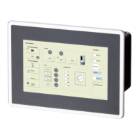
Covers configuring the drive for speed control, including detailed set-value selection methods.

Torque control with speed limitation

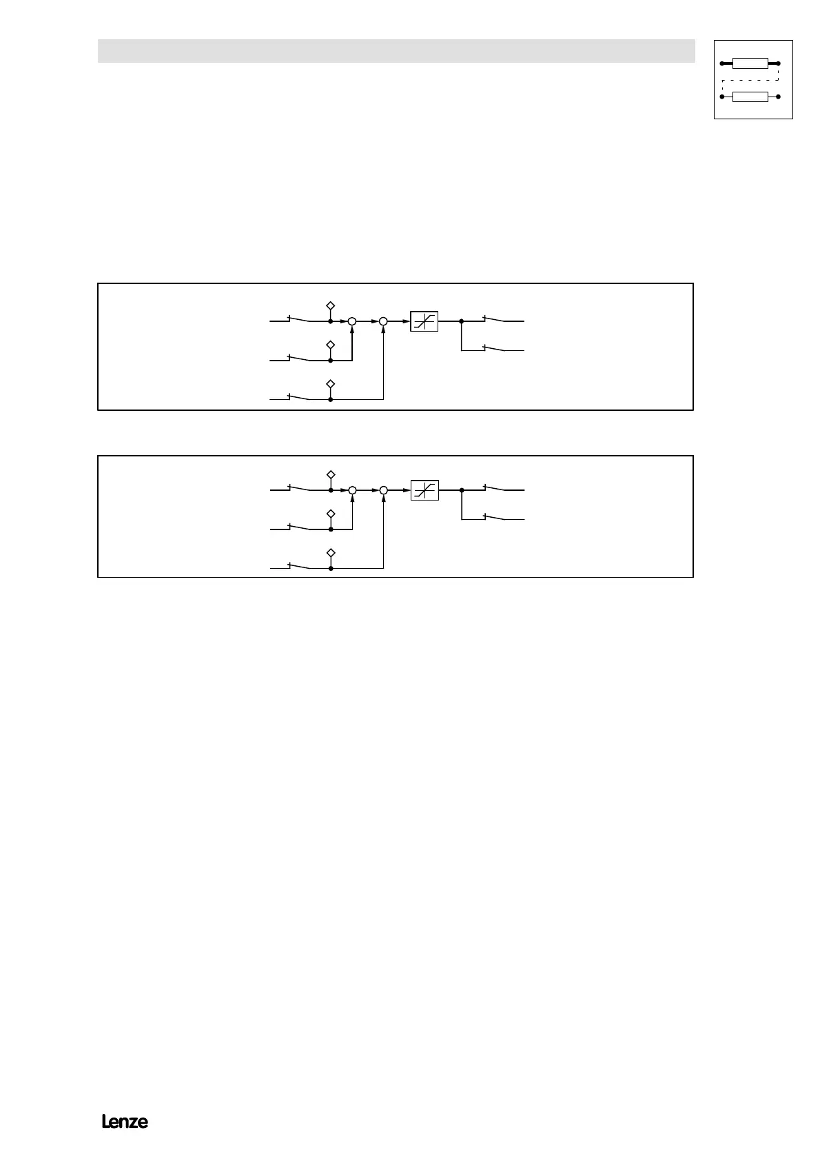
Explains how to set up the drive for torque control while maintaining speed limitations.

Troubleshooting and fault elimination

Troubleshooting

Guides users through identifying and resolving operational issues using controller displays and status information.

Fault analysis with the history buffer

Explains how to use the history buffer to trace and analyze faults for effective troubleshooting.

Signal-flow charts

Related product manuals